

Detection device and method for rotary encoder
A technology of rotary encoder and detection device, applied in the direction of instruments, etc., can solve the problems of single, troublesome encoder installation, low calibration and detection efficiency, etc., to achieve the effect of convenient detection and installation, and improve detection efficiency
- Summary
- Abstract
- Description
- Claims
- Application Information
AI Technical Summary
Problems solved by technology
Method used
Image

Examples
Embodiment 1
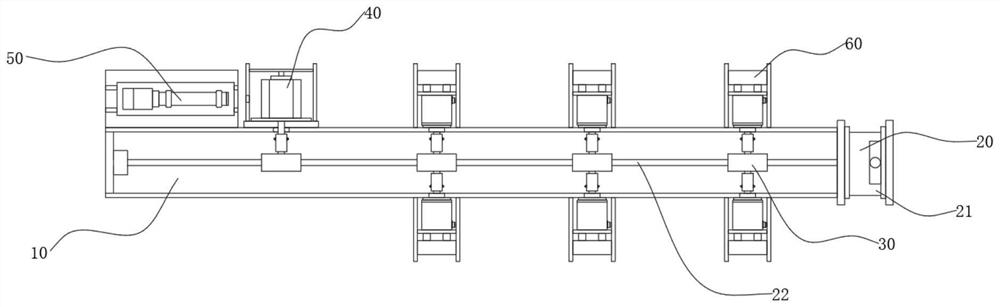
[0046] A detection device for a rotary encoder, comprising a detection table 10, and detection points arranged symmetrically on both sides of the detection table 10;
[0047] One end of the detection table 10 is equipped with a drive assembly 20, the drive assembly 20 includes a compact turntable 21, the compact turntable 21 is composed of a table body, a knob, a high-precision transmission gear and an output shaft, and the output shaft of the compact turntable 21 is fixedly connected with a drive rod 22, One end of the drive rod 22 is connected to the output shaft of the compact turntable 21, and the other end is connected to the bearing seat on the detection platform 10;
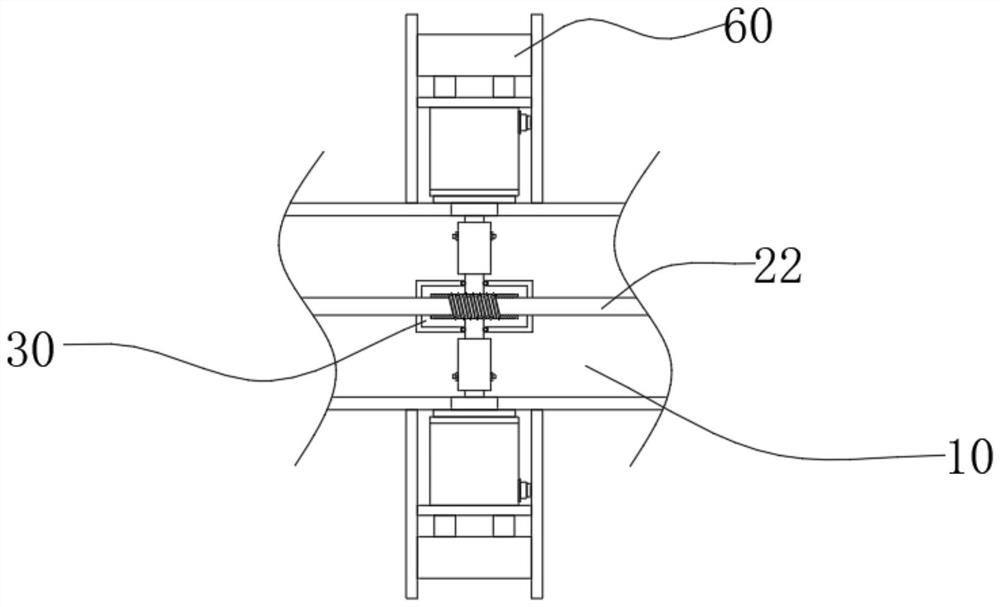
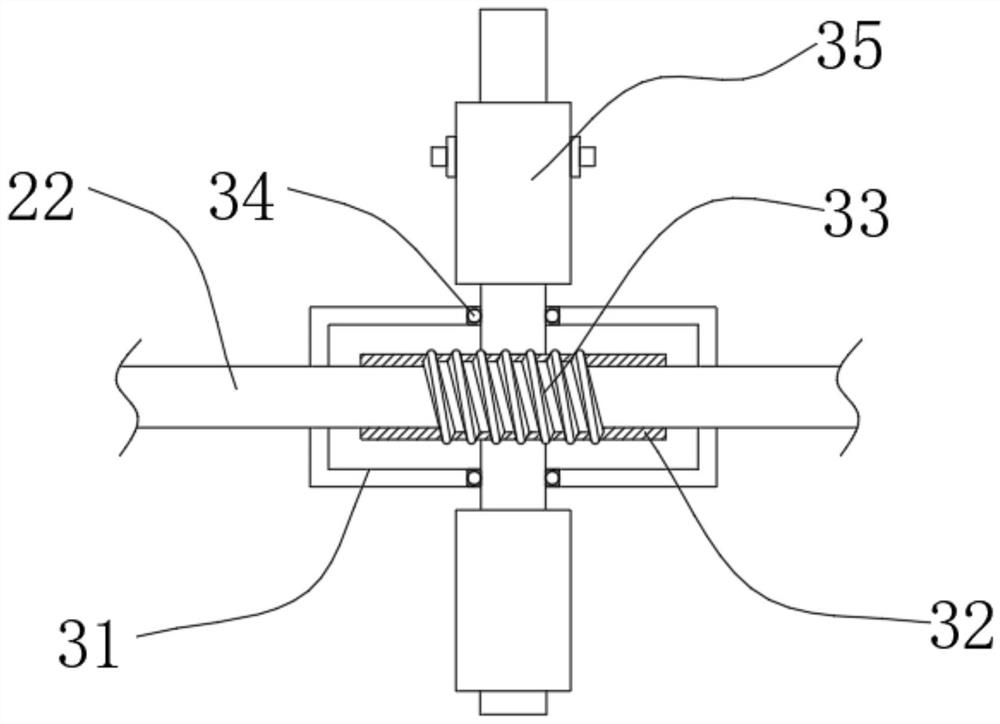
[0048] The interior of the detection table 10 is provided with at least two transmission assemblies 30 located on the same horizontal line. The transmission assembly 30 includes an outer shell 31, and the inside of the outer shell 31 is connected to a worm wheel 32 for rotation. The outer wall of the worm w...
Embodiment 2
[0052] On the basis of the first embodiment, the function of convenient clamping is added.
[0053]The detection point of the detection platform 10 is provided with a clamping assembly 60, the clamping assembly 60 includes a clamping frame 61, the outer wall of the clamping frame 61 is fixedly connected with a spring seat 62, and one side of the spring seat 62 is slidably connected with a lower pressing rod 63 , one end of the lower pressing rod 63 is fixedly connected with a clamping plate 64 .
[0054] refer to Figure 1-6 , when installing the encoder, by directly snapping the encoder into the clamping frame 61, the lower pressure rod 63 on the clamping frame 61 exerts pressure on the encoder on the clamping plate 64 to perform quick clamping installation, When the encoder is connected to the circuit and the shaft, it does not need to be taken by hand all the time, which greatly improves the inspection convenience of the inspection personnel.
PUM
 Abstract
Description
Claims
Application Information