Transformer tap switch flexible to install and transformer applying same

A tap changer and transformer technology, applied in the field of transformers, can solve the problems of inability to install, the wiring position is far away, and the length of the coil lead is increased, and achieves the effects of convenient installation and operation, convenient location setting, and simple transmission structure.

Pending Publication Date: 2022-04-19
江苏金诺电气科技有限公司
View PDF1 Cites 2 Cited by
  • Summary
  • Abstract
  • Description
  • Claims
  • Application Information

AI Technical Summary

Problems solved by technology

[0006] 1. The installation layout of the transformer tap-changer with the overall structure is very limited in the transformer. It is difficult to realize the installation position of the operating mechanism and the switch body. That is, the tap-changer can only be installed in a fixed position of the transformer. On the one hand, the operating mechanism The installation position of the tap changer cannot be flexibly selected. On the other hand, the terminal of the tap changer cannot be installed close to the outlet position of the coil winding of the transformer. It is necessary to increase the length of the lead wire of the coil winding, and it is difficult to further save the materials of the live body such as the transformer lead wire;
[0007] 2. The transformer tap-changer of the overall structure occupies a large space in the height of the transformer oil tank, which cannot further compact the structure of the transformer oil tank;
[0008] 3. For transformers with small size, the overall structure of the transformer tap changer, especially the bar type tap changer, its size is often larger than the size of the transformer, which makes installation difficult or even impossible.
However, in the existing triangular three-dimensional transformer tap changer, its three sets of switching mechanisms are connected together through the base, the height of the tap changer is relatively large, and the space occupied by the triangular three-dimensional transformer after installation is relatively large; After the switch is manufactured, its position with the coil branch wire of the transformer is fixed, and the installation position of the tap changer is limited. When the size of the transformer is large, the distance between each coil branch wire and the wiring position of the three-group switching mechanism is relatively long. The length of the coil lead is increased, and it is difficult to further save the material of the transformer lead and other charged bodies

Method used


Image

  • Transformer tap switch flexible to install and transformer applying same
  • Transformer tap switch flexible to install and transformer applying same
  • Transformer tap switch flexible to install and transformer applying same

Examples


Embodiment 1

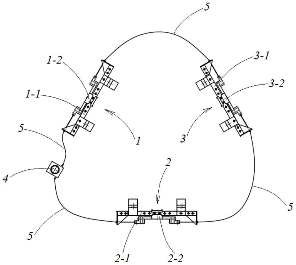
[0047] combine figure 1 As shown, a transformer tap changer with flexible installation in this embodiment includes a first tap mechanism 1, a second tap mechanism 2, a third tap mechanism 3, a switch operating mechanism 4 and a transmission bushing line 5. A tap mechanism 1, a second tap mechanism 2 and a third tap mechanism 3 all include a static contact assembly and a moving contact assembly, and the moving contact assembly and the static contact assembly are relatively sliding and switchable; specifically, the first The tap mechanism 1 includes a first static contact assembly 1-1 and a first movable contact assembly 1-2 that slides relative to the first static contact assembly 1-1, and the second tap mechanism 2 includes a second static contact assembly 1-2. The head assembly 2-1 and the second moving contact assembly 2-2 that is relatively slidingly matched with the second static contact assembly 2-1, and the third switching mechanism 3 includes the third static contact as...

Embodiment 2

[0057] A transformer tap changer with flexible installation and a transformer using it in this embodiment have the same basic structure and working principle as Embodiment 1, except that:

[0058] In this embodiment, the above-mentioned switch operating mechanism 4 is a slide type operating mechanism. Specifically, when the switch operating mechanism 4 is a sliding type operating mechanism, the switch operating mechanism 4 includes a switch base and a sliding body relatively slidably arranged in the switch base. The ends of the flexible wire cores are connected, and the end of the flexible sleeve in the corresponding drive sleeve line 5 is fixedly installed on the switch base. There is a push-pull part on the sliding body, and there is also a gear position mark and a gear position positioning mechanism on the switch base. The flexible core in the transmission sleeve line 5 on one side is driven by the push-pull sliding body, and the transmission sleeve line 5 on the other side...

Embodiment 3

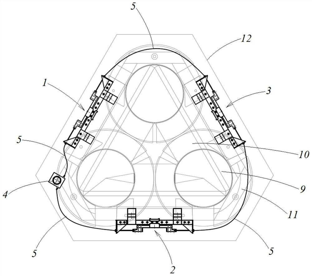
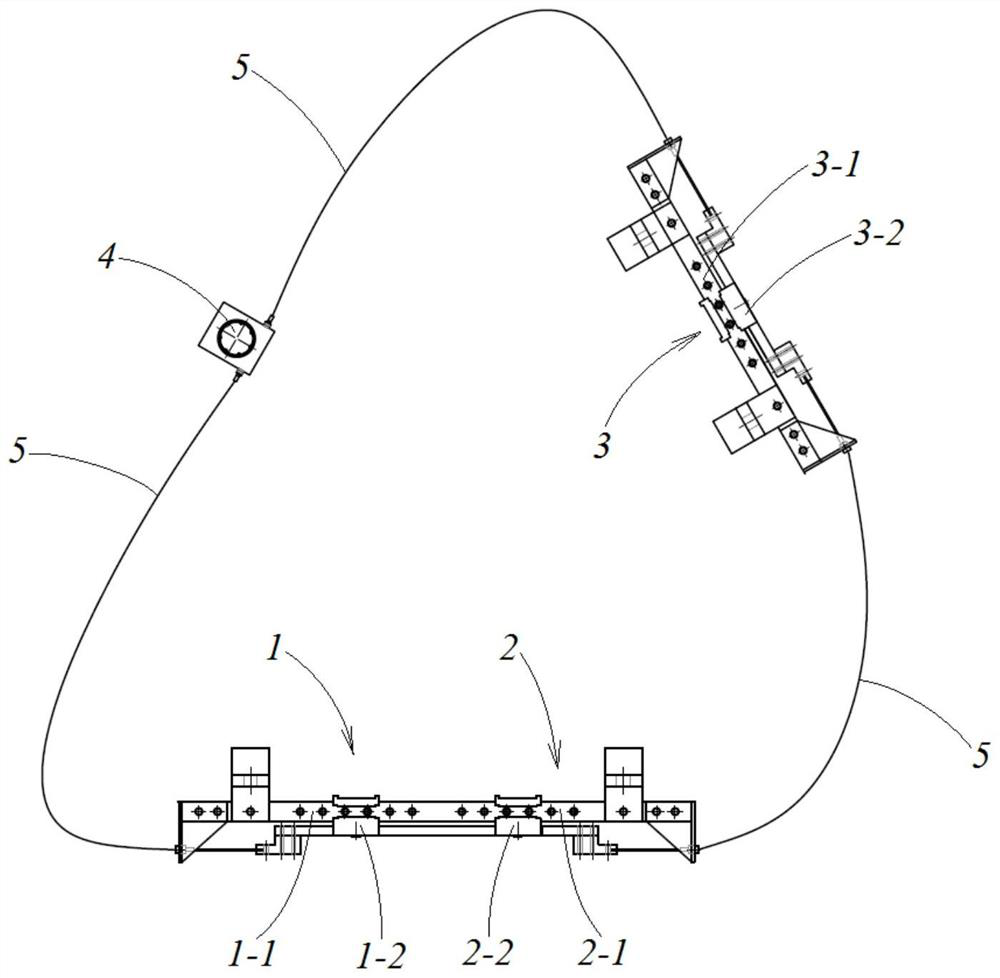
[0060] Such as image 3 and Figure 4 As shown, a flexible transformer tap changer of this embodiment and a transformer using it have the same basic structure and working principle as that of Embodiment 1, except that:

[0061] In this embodiment, any two of the first tap mechanism 1, the second tap mechanism 2, and the third tap mechanism 3 are connected as an integral structure, and pass through the transmission sleeve with the other and the switch operating mechanism 4 end to end. The transmission connection of the pipeline 5 is formed by synchronously controlling the moving contact assembly in the first tap mechanism 1, the second tap mechanism 2 and the third tap mechanism 3 to slide relative to the corresponding static contact assembly through the switch operating mechanism 4. Closed-loop tap-changer in the connection position of moving and static contacts.

[0062] Specific as image 3 , Figure 5 and Figure 6 As shown, the first tap-changing mechanism 1 and the s...


PUM


Abstract

The invention discloses a transformer tap switch flexible to install and a transformer applying the same, and belongs to the field of transformers. According to the invention, three groups of split-connection mechanisms of the transformer tap switch are divided into at least two independent switch parts, and the switch parts are in transmission connection with the switch operation mechanism through the transmission sleeve pipeline. According to the closed-loop tap switch, the switch operation mechanism synchronously controls the moving contact assemblies in the three groups of split-connection mechanisms to slide relative to the corresponding static contact assemblies so as to change the connection position of the moving contact and the static contact, so that the installation positions of the three groups of split-connection mechanisms in the transformer are more flexible; the wiring position of each tapping mechanism can be closer to the lead outgoing position of the corresponding coil winding of the transformer, so that the lead length of the coil winding is reduced, and the installation and operation of the tapping switch are facilitated; and the occupied space of the tap switch in the transformer can be reduced, so that the structure of the transformer is more compact, and the transformer can be suitable for the existing triangular three-dimensional transformer and planar rectangular transformer.

Description

[0001] This application claims the priority of the Chinese patent application number 202123083236.0 filed on December 09, 2021, entitled "A Flexible Installable Transformer Tap-Changer and a Transformer Using It". technical field [0002] The invention relates to a transformer tap changer, more specifically, to a transformer tap changer with flexible installation and a transformer using the same. Background technique [0003] The transformer tap changer changes the number of high-voltage coil turns by changing the connection position of the tap, thereby adjusting the output voltage of the transformer. It is one of the indispensable main accessories on the transformer. [0004] Existing transformer tap-changers can be divided into strip tap-changers, cage tap-changers, disc-shaped tap-changers and delta-shaped transformer tap-changers according to different structural forms. These transformer tap-changers are mainly composed of operating mechanism and switch The main body is ...

Claims


Application Information

Patent Timeline
Patent Type & Authority Applications(China)
IPC IPC(8): H01H3/02H01F27/30H01F27/29H01F27/14
CPCH01H3/02H01F27/306H01F27/29H01F27/14
Inventor 戴波
Owner 江苏金诺电气科技有限公司
Why Eureka
Try Eureka