Directional diagram reconfigurable antenna with end-fire beam scanning function

A technology for reconstructing antennas and beam scanning, applied in the directions of antennas, antenna components, and radiating element structures, etc., it can solve the problems of large gain fluctuations and application limitations of reconfigurable antennas with patterns, and achieve good consistency and small antennas. Size, easy processing effect

Active Publication Date: 2022-04-19
NANTONG UNIVERSITY +1
View PDF11 Cites 0 Cited by
  • Summary
  • Abstract
  • Description
  • Claims
  • Application Information

AI Technical Summary

Problems solved by technology

However, limited by the overly discrete beam, the gain fluctuation of the pattern reconfigurable antenna in its coverage area is often large, and many designs even have some coverage holes, which greatly limits the application of the pattern reconfigurable antenna. limits

Method used


Image

  • Directional diagram reconfigurable antenna with end-fire beam scanning function
  • Directional diagram reconfigurable antenna with end-fire beam scanning function
  • Directional diagram reconfigurable antenna with end-fire beam scanning function

Examples


Embodiment Construction

[0022] The present invention will be described in detail below in conjunction with the accompanying drawings for further explanation, so that those skilled in the art can understand the present invention more deeply and can implement it, but the following examples are only used to explain the present invention, not as the present invention limit.

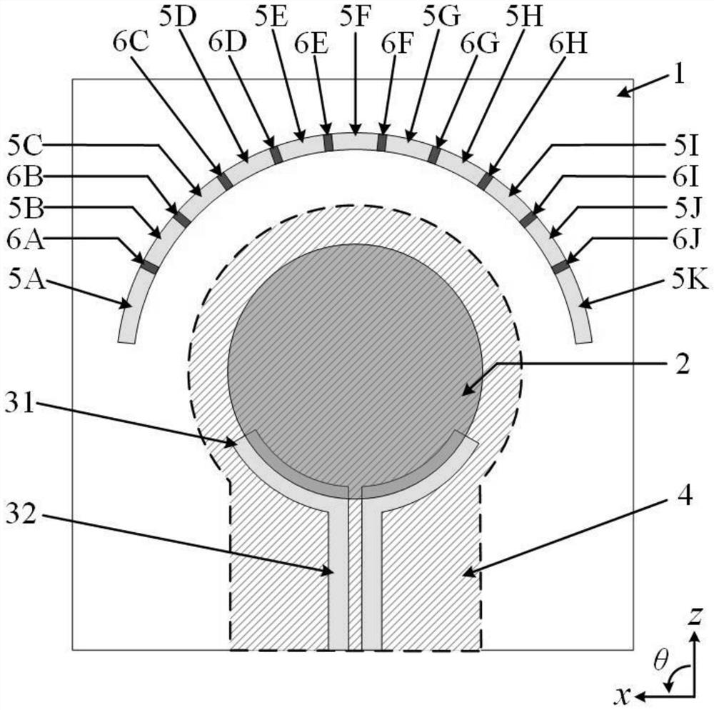
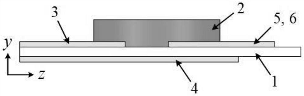
[0023] Such as Figure 1 to Figure 2 As shown, a pattern reconfigurable antenna with end-fire beam scanning function includes a metal ground 4 and a dielectric substrate 1 stacked from bottom to top. The upper surface of the dielectric substrate 1 is pasted with a dielectric resonator 2, a differential feed The electrical structure 3 and the switchable director; the dielectric resonator 2 is excited by the differential feed structure 3; the differential feed structure 3 includes a pair of metal arms 31 partially located at the bottom of the dielectric resonator 2 and a pair of parallel microstrip lines 32; The metal arm 31 is conne...


PUM

PropertyMeasurementUnit
relative permittivityaaaaaaaaaa

Abstract

The invention belongs to the technical field of antenna communication, and particularly relates to a directional diagram reconfigurable antenna with an end-fire beam scanning function. The antenna comprises a metal ground and a dielectric substrate which are stacked from bottom to top. A dielectric resonator, a differential feed structure and a switchable director are pasted on the upper surface of the dielectric substrate. The dielectric resonator is excited by the differential feed structure; the differential feed structure comprises a pair of metal arms partially located at the bottom of the dielectric resonator and a pair of parallel microstrip lines; the metal arm is connected with the parallel microstrip line; the vertical projection area of the metal ground on the dielectric substrate is larger than the vertical projection area of the dielectric resonator and the differential feed structure on the dielectric substrate. The switchable director is located at one side, far away from the differential feed structure, of the dielectric resonator, and the distance from the switchable director to the center of the dielectric resonator is greater than the distance from the metal arm to the center of the dielectric resonator.

Description

technical field [0001] The invention belongs to the technical field of antenna communication, and in particular relates to a reconfigurable antenna with an endfire beam scanning function. Background technique [0002] In recent years, wireless communication technology has developed rapidly, and antenna, as a component used to transmit or receive radio waves, plays a pivotal role in wireless communication systems. At present, the important direction of wireless communication system development is large capacity, multi-function, and ultra-wideband. In order to meet this demand, the number of antennas mounted on the same platform will increase accordingly, and the increase in the number of antennas will inevitably lead to an increase in system cost, weight, and volume. , but also brought about electromagnetic compatibility issues. In order to overcome this constraint and make the performance of the entire communication system less constrained by the antenna, reconfigurable ant...

Claims


Application Information

Patent Timeline
Patent Type & Authority Applications(China)
IPC IPC(8): H01Q1/24H01Q1/38H01Q1/50H01Q3/24
CPCH01Q1/38H01Q1/50H01Q1/241H01Q3/24Y02D30/70
Inventor 陈建新柯彦慧杨玲玲杨汶汶杨永杰
Owner NANTONG UNIVERSITY
Why Eureka
Try Eureka