

Knee joint rehabilitation device for rheumatism and immunology department
A technology of rheumatism immunity and rehabilitation equipment, which is applied in the direction of sports accessories, passive exercise equipment, muscle training equipment, etc. It can solve the problems of poor training effect and single training, and achieve good training effect, easy detachable connection, and convenient ankle fixation quick effect
- Summary
- Abstract
- Description
- Claims
- Application Information
AI Technical Summary
Problems solved by technology
Method used
Image

Examples
Embodiment Construction
[0027] The following will clearly and completely describe the technical solutions in the embodiments of the present invention with reference to the accompanying drawings in the embodiments of the present invention. Obviously, the described embodiments are only some, not all, embodiments of the present invention. Based on the embodiments of the present invention, all other embodiments obtained by persons of ordinary skill in the art without making creative efforts belong to the protection scope of the present invention.
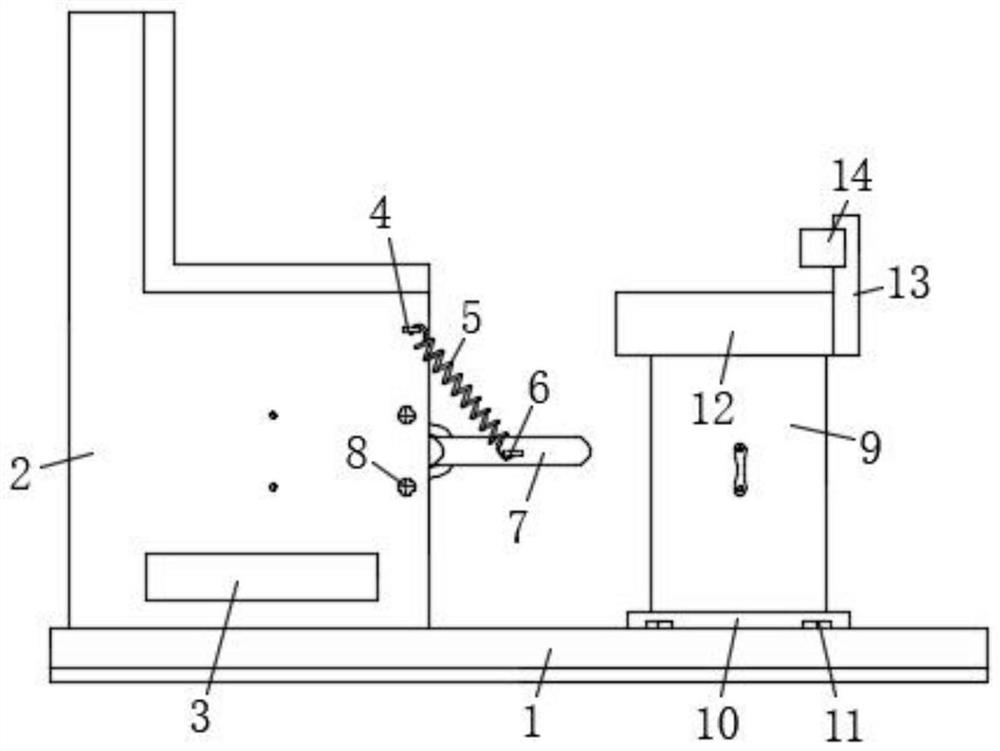
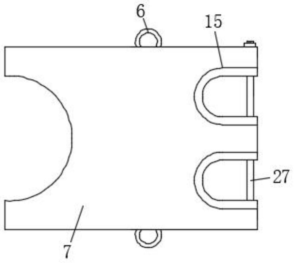
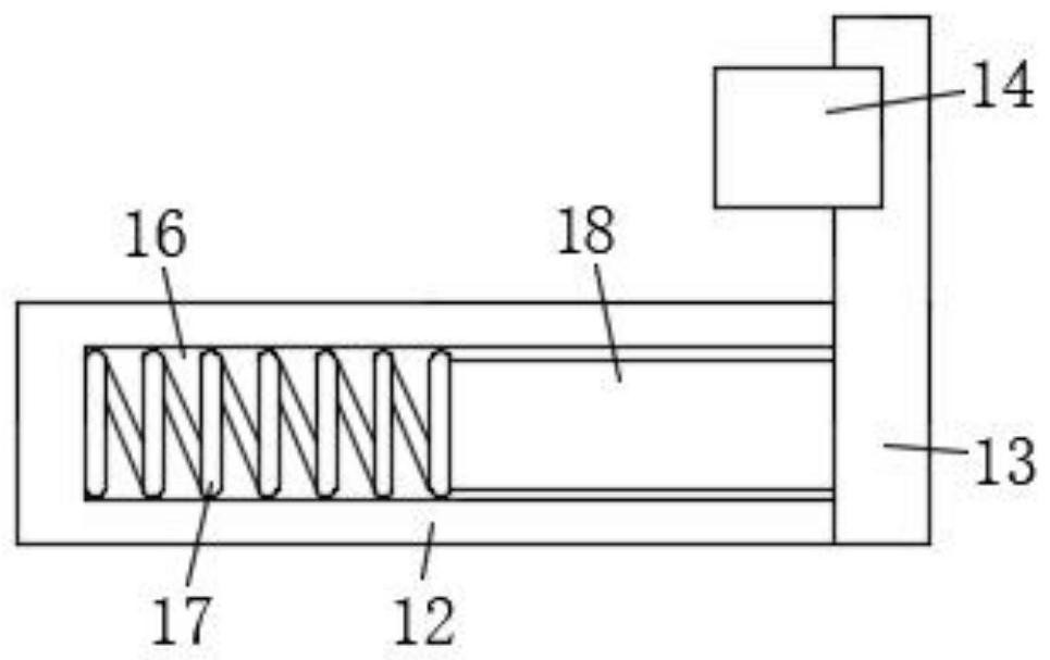
[0028] see Figure 1-Figure 6 As shown, the present invention provides the following technical solutions: a knee joint rehabilitation device for rheumatology and immunology department, comprising a base plate 1, an ankle fixation assembly, a lateral training assembly and a moving assembly, one end of the upper surface wall of the base plate 1 is provided with a stool 2, and the stool The front surface wall of 2 is indented to form a second groove 19, and the i...
PUM
 Abstract
Description
Claims
Application Information