Supercharge Your Innovation With Domain-Expert AI Agents!

Clamp capable of sucking waste liquid

A fixture and waste liquid technology, applied in the direction of manufacturing tools, workpiece clamping devices, cleaning methods and utensils, etc., can solve the problems of easy accumulation of coolant and affect the line of sight, etc., achieve clear sight, improve processing accuracy, and improve use convenience Effect

Pending Publication Date: 2022-04-22
浙江坤博精工科技股份有限公司
View PDF0 Cites 0 Cited by
  • Summary
  • Abstract
  • Description
  • Claims
  • Application Information

AI Technical Summary

Problems solved by technology

However, for a flat plate-shaped workpiece, the coolant is easy to accumulate on the surface, thereby affecting the line of sight

Method used


Image

  • Clamp capable of sucking waste liquid
  • Clamp capable of sucking waste liquid
  • Clamp capable of sucking waste liquid

Examples


Embodiment Construction

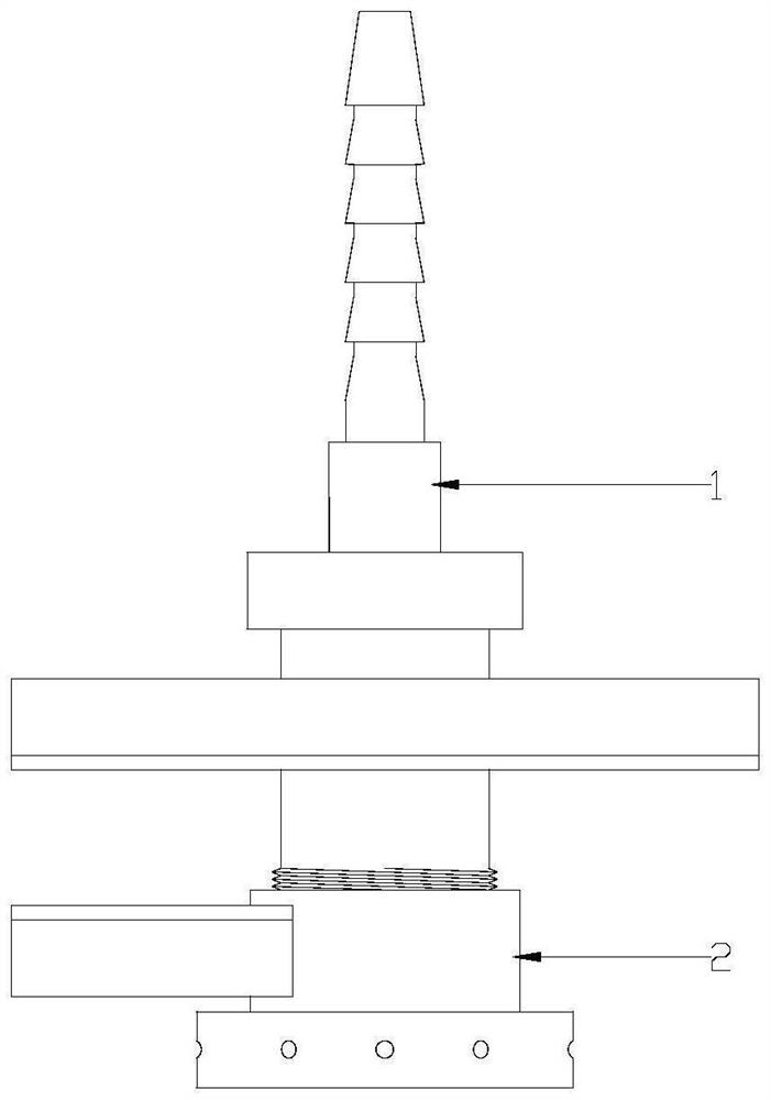
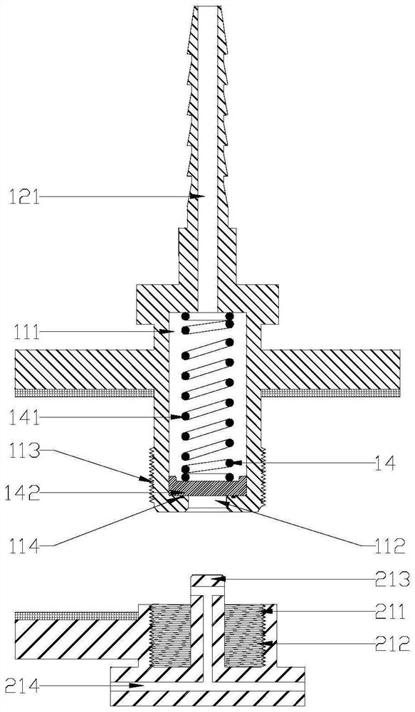
[0021] refer to figure 1 , figure 2 and image 3 , the present invention is a clamp that can suck waste liquid, including a clamp body, a hose, a suction pump and a controller, the clamp body includes a chuck 1 and a base 2, and on the outer walls of the chuck 1 and the base The upper splint 13 and the lower splint 22 are arranged horizontally respectively, the chuck 1 and the base 2 are threadedly connected up and down, and a liquid passage is provided inside, and several inlets of the liquid passage are respectively arranged on the outer wall of the base 2 , the outlet of the liquid passage is connected to a suction pump through a hose, and the suction pump is electrically connected to a controller.

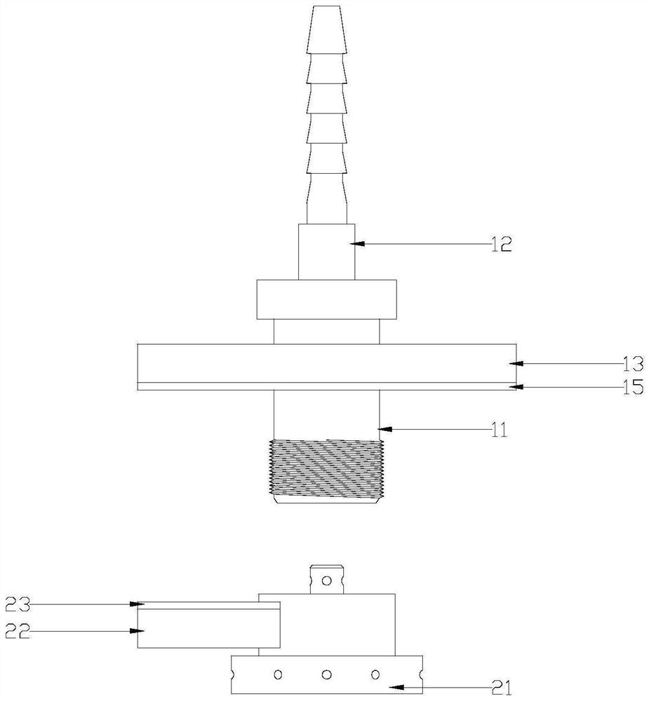
[0022] The chuck 1 includes a main body cylinder 11, a pipe joint 12 and an upper clamping plate 13, the pipe joint 12 is fixed on the top of the main body cylinder 11, and the upper clamping plate 13 is horizontally fixed on the outer wall of the main body cylinder 11. The...


PUM


Abstract

The clamp comprises a clamp body, a hose, a suction pump and a controller, the clamp body comprises a clamping head and a base, an upper clamping plate and a lower clamping plate are horizontally arranged on the outer wall of the clamping head and the outer wall of the base respectively, the clamping head and the base are in threaded connection up and down, and a liquid channel is formed in the clamping head and the base in a penetrating mode; a plurality of inlets of the liquid channel are formed in the outer wall of the base, an outlet of the liquid channel is connected with a suction pump through a hose, and the suction pump is electrically connected with a controller. The chuck and the base which are provided with the upper threads and the lower threads are arranged to serve as the clamp body, the liquid channel is arranged in the clamp body, and the clamp body can be matched with the hose and the suction pump at the same time during workpiece clamping, so that waste liquid such as redundant cooling liquid is sucked away, clear sight is guaranteed, and then the machining precision is improved.

Description

【Technical field】 [0001] The invention relates to the technical field of clamps, in particular to the technical field of a clamp capable of sucking waste liquid. 【Background technique】 [0002] Injection molding machine, also known as injection molding machine or injection machine, is the main molding equipment for making thermoplastics or thermosetting plastics into various shapes of plastic products using plastic molding molds. It is divided into vertical, horizontal and all-electric types. Injection molding is to plasticize the plastic in the heating barrel of the injection molding machine, and then inject it into the cavity of the closed mold by a plunger or a reciprocating screw, thereby forming a plastic processing method of injection molded workpieces with complex shapes, precise dimensions, or inserts. . [0003] At present, when the injection molded workpiece is clamped and processed by a clamp, in order to avoid deformation of the workpiece due to heat, it is nece...

Claims


Application Information

Patent Timeline
IPC IPC(8): B25B11/00B08B5/04B08B13/00
CPCB25B11/00B08B5/04B08B13/00
Inventor 罗鑫磊厉伟
Owner 浙江坤博精工科技股份有限公司
Features
  • R&D
  • Intellectual Property
  • Life Sciences
  • Materials
  • Tech Scout
  • Unparalleled Data Quality
  • Higher Quality Content
  • 60% Fewer Hallucinations
Learn More