Electric vehicle electronic lock control circuit in standby power mode and electric vehicle
A technology for controlling circuits and electronic locks, which is applied to circuit devices, non-mechanical transmission-operated locks, building locks, etc. It can solve problems such as power outages and smart phones cannot control electronic locks, and achieve the effect of improving user experience
- Summary
- Abstract
- Description
- Claims
- Application Information
AI Technical Summary
Problems solved by technology
Method used
Image
Examples
Embodiment 1
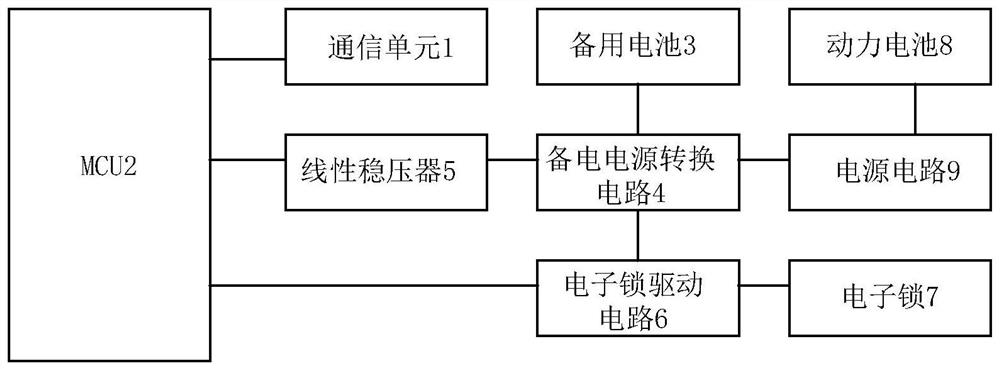
[0043] figure 1 It is a schematic diagram of the electric vehicle electronic lock control circuit in the backup mode provided by Embodiment 1 of the present invention.
[0044] refer to figure 1 , the circuit includes: communication unit 1, MCU2, backup battery 3, backup power conversion circuit 4, linear voltage regulator 5, electronic lock drive circuit 6 and electronic lock 7;
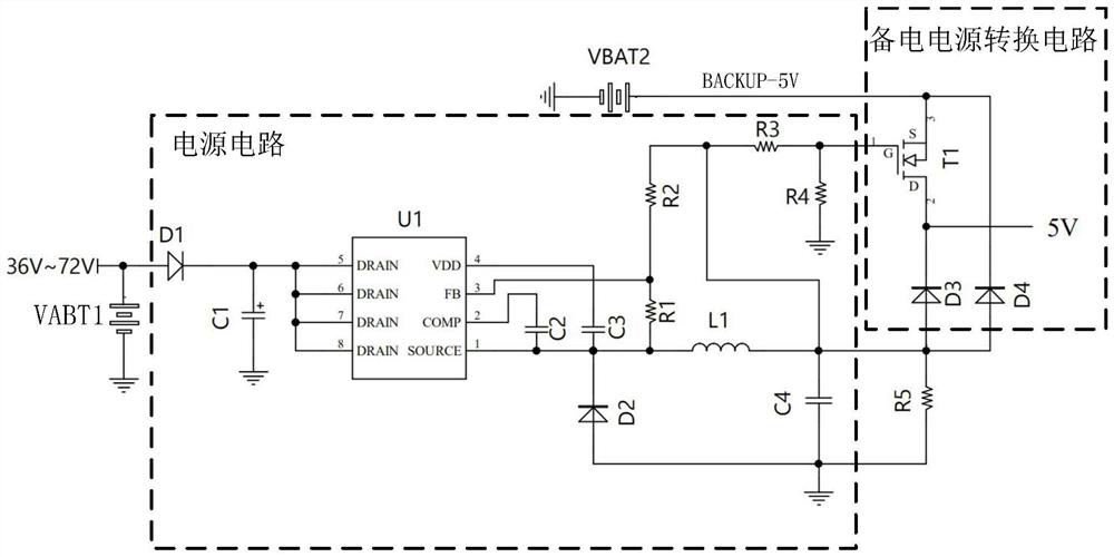
[0045] The communication unit 1, the electronic lock driving circuit 6 and the linear voltage regulator 5 are connected to the MCU2 respectively, and the backup battery 3, the linear voltage regulator 5 and the electronic lock driving circuit 6 are connected to the backup power conversion circuit 4 respectively; wherein, the communication Unit 1, MCU2, linear voltage regulator 5, backup power supply conversion circuit 4, power supply circuit and electronic lock drive circuit 6 are integrated on the same circuit board;
[0046] The backup power supply conversion circuit 4 is used to provide the commu...
PUM
 Abstract
Description
Claims
Application Information
 - R&D
- Intellectual Property
- Life Sciences
- Materials
- Tech Scout
- Unparalleled Data Quality
- Higher Quality Content
- 60% Fewer Hallucinations
Browse by: Latest US Patents, China's latest patents, Technical Efficacy Thesaurus, Application Domain, Technology Topic, Popular Technical Reports.
© 2025 PatSnap. All rights reserved.Legal|Privacy policy|Modern Slavery Act Transparency Statement|Sitemap|About US| Contact US: help@patsnap.com


