
Construction method of upper-layer prefabricated vertical component

A technology of vertical components and construction methods, which is applied to the preparation of building components on site, building structures, pillars, etc., and can solve the problem of long construction period of upper prefabricated vertical components 3, the inability to pour concrete in one piece, and the impact on construction speed and other problems, to achieve the effect of convenient and reliable layout and installation, shortening the construction period, and simple and convenient installation

Pending Publication Date: 2022-04-22
曹大燕
View PDF0 Cites 0 Cited by
  • Summary
  • Abstract
  • Description
  • Claims
  • Application Information

AI Technical Summary

Problems solved by technology

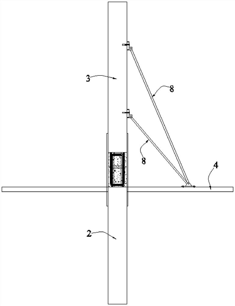
[0004] In the prior art, when the upper floor 4 adopts a cast-in-place floor slab or floor deck structure, after the reinforcement of the cast-in-place floor slab or the floor deck is installed, the concrete pouring of the cast-in-place floor or floor deck structure is completed first, Then install the upper strut 8 in the figure on the upper floor 4 to provide stable oblique support for the upper prefabricated vertical member 3, so as to avoid the reinforcement of the upper floor 4 before the concrete is poured or the floor deck It is impossible to provide a reliable fulcrum for the upper strut 8; this method has the following disadvantages: since it is necessary to complete the concrete pouring of the upper floor 4 first, wait until the strength of the concrete reaches the standard, and then install the oblique support of the upper prefabricated vertical member 3. The upper strut 8 leads to: the construction period of the upper prefabricated vertical member 3 is long, which affects the construction speed of the building, and the concrete of the connecting node between the upper prefabricated vertical member 3 and the lower vertical member 2 and the concrete of the upper floor 4 cannot Realize integrated pouring, affecting the structural strength of the building

Method used


Image

  • Construction method of upper-layer prefabricated vertical component
  • Construction method of upper-layer prefabricated vertical component
  • Construction method of upper-layer prefabricated vertical component

Examples


Embodiment 1

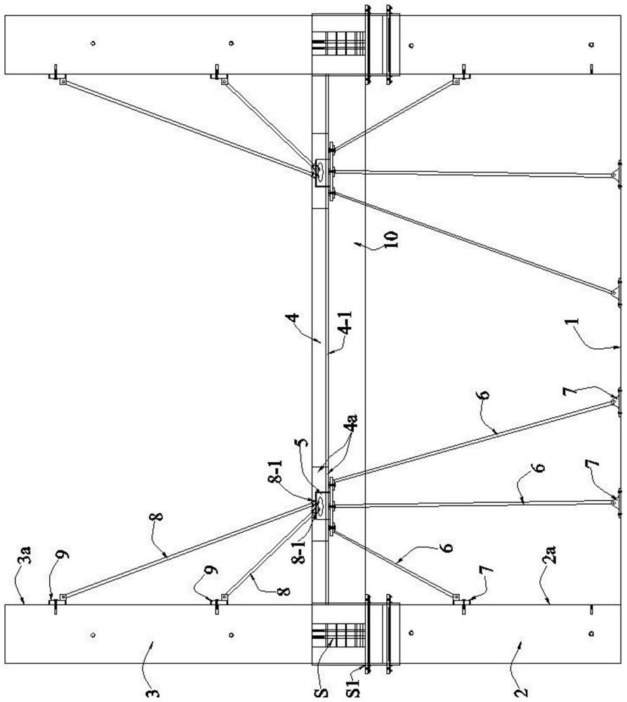
[0041] like figure 2 As shown, what the present invention discloses is a kind of upper layer prefabricated vertical component construction method, comprising:

[0042] Step S1, complete the construction of the lower floor 1 and the lower vertical member 2, and install the reinforcement part of the upper floor 4 and the floor cast-in-place concrete form 4-1, and reserve the reinforcement part and the floor cast-in-place concrete form 4-1 There are a plurality of floor holes 4a; wherein, the upper floor 4 is the upper floor of the lower floor 1, and adopts a cast-in-place floor structure or a floor deck structure;

[0043] Wherein, if the upper floor 4 itself is designed with reserved holes near the upper prefabricated vertical member 3, these reserved holes can be used as the floor holes 4a, if the number of reserved holes near the upper prefabricated vertical member 3 is insufficient , the floor hole 4a can be additionally set, and the floor hole 4a can be filled by pouring ...

Embodiment approach

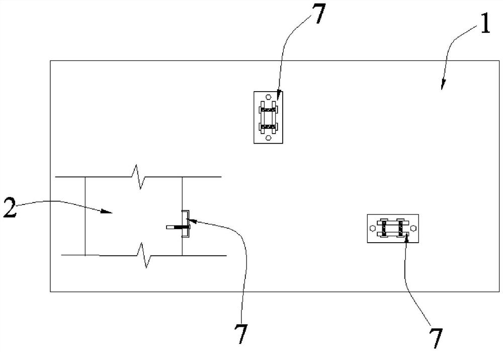
[0062] The lower support structure includes three lower braces 6, one of which is connected between the side 2a of the lower vertical member 2 and the bottom of the support 5, and the other two lower braces 6 are connected between the between the lower floor slab 1 and the bottom of the support member 5, and the three lower struts 6 are not parallel to each other and are not on the same plane, so that the fulcrums of the three lower struts 6 on the horizontal plane are arranged in a triangular orientation, see image 3 , can improve the stability of the underlying support structure.

[0063] The above is the basic implementation mode of the second embodiment, further optimization, improvement and limitation can be done on the basis of the basic implementation mode:

[0064] Preferably: one of the lower braces 6 is perpendicular to the lower floor 1, so that the lower supporting structure can obtain better supporting effect.

[0065] Preferred: see figure 2 and Figure 4 , ...

Embodiment 3

[0067] On the basis of the above-mentioned embodiment 1 or embodiment 2, this embodiment 3 also adopts the following preferred implementation modes:

[0068] The upper support device includes two upper struts 8, both of which are telescopic rods whose length can be adjusted and locked; The mounting seat 9 is fixed on the side surface 3a of the upper prefabricated vertical member 3 by means of bolt connection, the lower end of the upper strut 8 is provided with a buckle 8-1 that can be opened and closed, and the support member 5 is provided with Evacuation hole 5a, to form buckle lock side 5-1 on the top of described support member 5, described buckle ring 8-1 is fastened on this buckle lock side 5-1; And, described two upper struts 8 The corresponding two upper mounts 9 are on the same vertical line. Therefore, the upper prefabricated vertical member 3 can be stably supported obliquely by the two upper struts 8 .

[0069] The above is the basic implementation of the third em...


PUM


Abstract

The invention discloses a construction method of an upper-layer prefabricated vertical component, which comprises the following steps of: installing a lower-layer supporting device in each floor slab hole through a step S2 after the step S1, limiting the displacement of a supporting piece by using a lower-layer supporting structure, and hoisting the upper-layer prefabricated vertical component through a lower-layer supporting structure after the upper-layer prefabricated vertical component is hoisted in a step S3. Effective lateral supporting and anti-overturning supporting are provided for the upper-layer prefabricated vertical component through a plurality of independent upper-layer supporting devices with supporting pieces as stable fulcrums in the step S4, so that formwork installation and concrete pouring can be carried out under the condition that the upper-layer prefabricated vertical component is in a stable state in the step S5 and the step S6; therefore, one-time pouring of the concrete of the post-pouring connection section and the cast-in-place concrete of the upper floor slab can be achieved, improvement of the structural strength of a building is facilitated, and the construction period can be shortened.

Description

technical field [0001] The invention relates to a prefabricated construction method of an assembled building, in particular to a construction method of an upper prefabricated vertical component. Background technique [0002] At present, prefabricated buildings are vigorously developed in the field of industrial and civil construction, and prefabricated vertical components such as prefabricated columns and prefabricated walls are also widely used in public buildings and civil buildings. [0003] like figure 1 As shown, during the construction of the current prefabricated building structure, after the construction of the lower floor and the lower vertical member 2 is completed, the upper prefabricated vertical member 3 needs to be hoisted to the top surface of the lower vertical member 2, and the upper floor After the prefabricated vertical member 3 is installed with a stable diagonal support, ie, the upper strut 8 in the figure, concrete is poured to combine the upper prefab...

Claims


Application Information

Patent Timeline
Patent Type & Authority Applications(China)
IPC IPC(8): E04B1/00E04B1/16E04G25/00E04G25/02E04G21/26
CPCE04B1/00E04B1/161E04G25/00E04G25/02E04G21/26E04G2025/003E04G2025/006
Inventor 曹大燕
Owner 曹大燕
Learn More