Integrated detachable assembly type T-shaped die wall and mounting method

A prefabricated and integrated technology, applied in the processing of walls, building materials, building components, etc., can solve the problems that affect the beauty of the wall, the integrity of the wall, the inconvenience of quick installation and disassembly, and the large amount of labor and time spent. , achieve high and low temperature resistance, improve stability, and reduce the effect of loosening

Pending Publication Date: 2022-04-22
华工匠建筑装配工程(深圳)有限公司
0 Cites 0 Cited by

AI-Extracted Technical Summary

Problems solved by technology

[0003] The prior art has the following deficiencies: the existing prefabricated T-form wall is not convenient for quick installation and disassembly, and requires a lot of labor and time for installation, and most of the installat...

Method used

Further, the quantity of right-angle reinforcing plate 420 is set to two groups, two groups of right-angle reinforcing plates 420 are evenly installed on both sides of center plate 410, and the material of right-angle reinforcing plate 420 is set to titanium alloy, specifically, right-angle reinforcing plate The role of 420 is to reinforce the center plate 410 and improve the stability of the center plate 410. It is set as a titanium alloy material because titanium alloy has the advantages of high strength, corrosion resistance and high and low temperature resistance, and the right angle reinforcement plate 420 is improved. Durability and support strength.
Further, triangular notch 430 is identical with triangular protrusion 330 volumes, and triangular notch 430 outer surface can fit mutually with triangular protrusion 330 inner side, and the quantity of inserting block 320 and slot 440 is all set to several groups, inserting block 320 is equal to the volume of the slot 440, the insert block 320 can be inserted into the inner wall of the slot 440, the inner diameter of the arc groove 451 is larger than the fixed cylinder 110, the arc groove 451 is adjacent to the mounting hole 452, and the length of the fixed cylinder 110 is less than The width of the arc-shaped slot 451 and the number of mounting blocks 450 are all set to multiple grou...

Abstract

The invention discloses an integrated detachable assembly type T-shaped mold wall and an installation method, and relates to the technical field of constructions.The integrated detachable assembly type T-shaped mold wall comprises a T-shaped mold wall body, a first wall body, a second wall body, an installation device and a locking device.The T-shaped mold wall body comprises the first wall body and the second wall body which are perpendicularly installed, and a center plate is installed on the inner wall of the first wall body; a right-angle reinforcing plate is fixedly connected to one side of the center plate, a triangular notch is formed in the outer surface of the front end of the first wall body, an inserting groove is formed in the outer surface of the triangular notch, a mounting block is mounted at the front end of the center plate, an arc-shaped groove is formed in the outer surface of one side of the mounting block, and a mounting hole is formed in the outer surface of the mounting block. A mounting device is mounted on the inner wall of the second wall body, and a triangular protrusion is mounted at the front end of the second wall body. The T-shaped mold wall has the advantages that mounting and dismounting are convenient and fast, the labor amount is small, the integrity and attractiveness are high, the phenomenon of loosening in use after mounting is reduced, the stability of the T-shaped mold wall is improved, and the service life of the T-shaped mold wall is prolonged.

Application Domain

WallsBuilding material handling

Technology Topic

EngineeringStructural engineering +1

Image

  • Integrated detachable assembly type T-shaped die wall and mounting method
  • Integrated detachable assembly type T-shaped die wall and mounting method
  • Integrated detachable assembly type T-shaped die wall and mounting method

Examples

  • Experimental program(1)

Example Embodiment

[0033] The preferred embodiments of the present invention will be described below in conjunction with the accompanying drawings. It should be understood that the preferred embodiments described here are only used to illustrate and explain the present invention, and are not intended to limit the present invention.
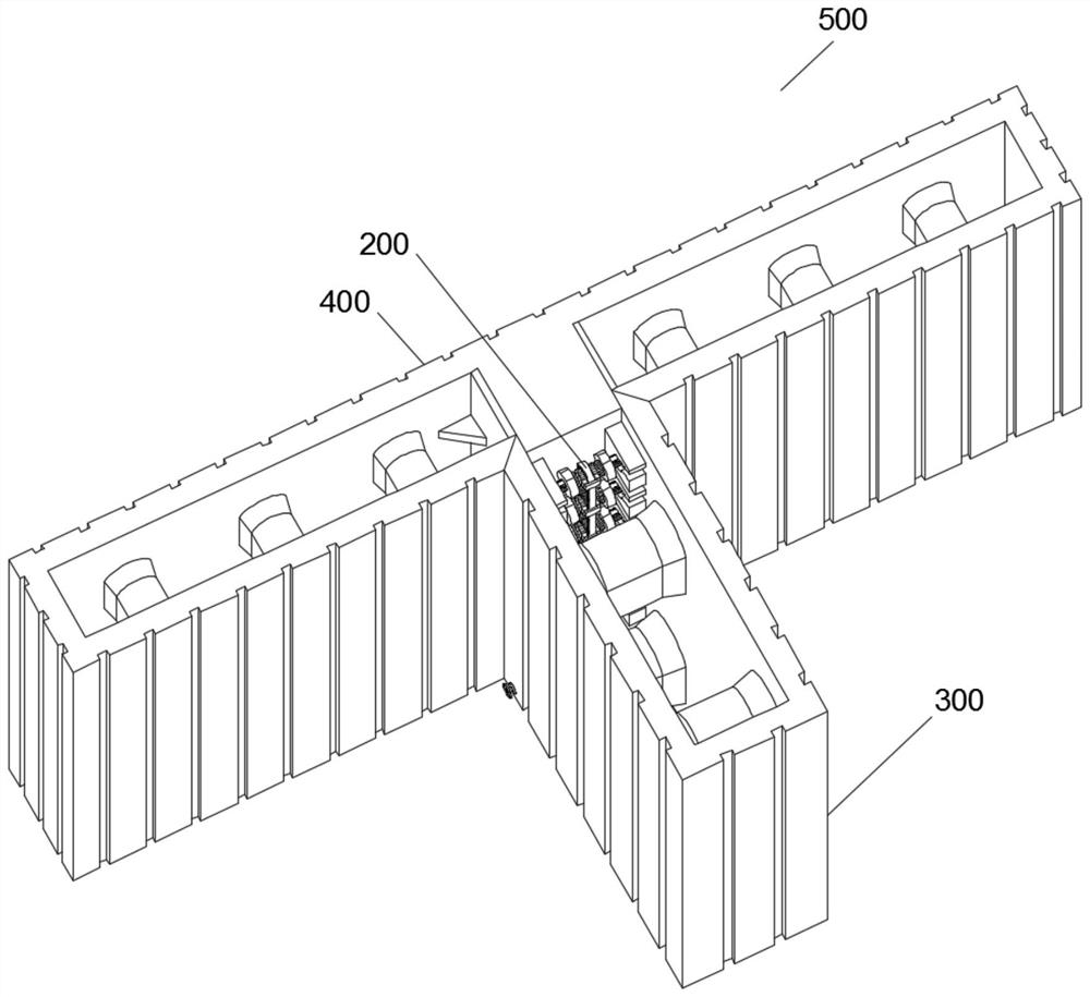
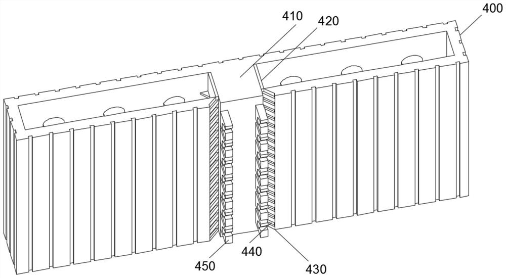
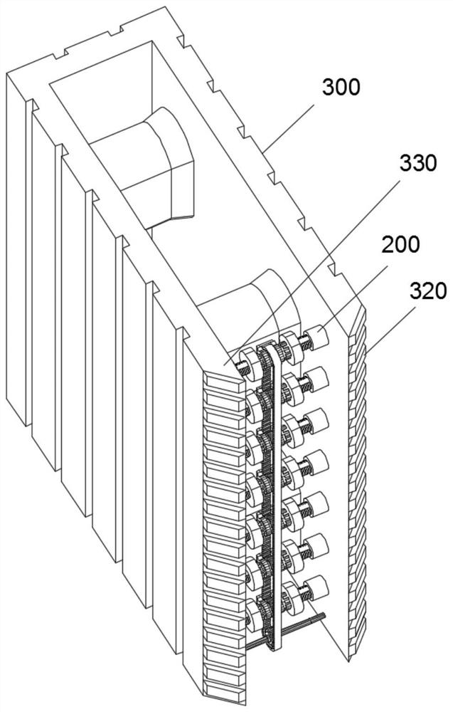
[0034] Refer to attached Figure 1-9 , the present invention provides an integrated detachable assembled T-form wall and its installation method. , including T-shaped wall 500, wall one 400, wall two 300, installation device 200 and locking device 100, T-shaped wall 500 includes wall one 400 and wall two 300 installed vertically to each other, wall one A center plate 410 is installed on the inner wall of 400, and one side of the center plate 410 is fixedly connected with a right-angle reinforcement plate 420. A triangular notch 430 is provided on the outer surface of the front end of the wall body 400, and a slot 440 is provided on the outer surface of the triangular notch 430. The front end of the center plate 410 is installed with a Mounting block 450, the outer surface of one side of the mounting block 450 is provided with an arc groove 451, the outer surface of the mounting block 450 is provided with a mounting hole 452, the inner wall of the wall body 2 300 is equipped with a mounting device 200, and the front end of the wall body 2 300 is equipped with a triangular protrusion 330, one side of the triangular protrusion 330 is fixedly connected to the plug 320, the installation device 200 also includes a locking device 100, and the locking device 100 also includes a fixing cylinder 110 fixedly connected to the inner side of the wall 2 300, and the inner wall of the fixing cylinder 110 is provided with an inner Thread 115, internal thread 115 inner wall is provided with external thread rod 120, and external thread rod 120 one end is equipped with fixed disk 125, and fixed disk 125 left side outer surface is provided with circular hole 126, and circular hole 126 inner wall is provided with sliding groove 127, and circular hole The inner wall of 126 is provided with a mounting column 140, the outer surface of the mounting column 140 is fixedly socketed with the gear ring 141, the outer surface of the mounting column 140 is equipped with a sliding rib 142, the outer surface of the mounting column 140 is movably socketed with the rotating ring 150, and the front end of the rotating ring 150 is fixedly connected Limiting plate 151, the inner wall of limiting plate 151 is provided with toothed belt 50, and the inner wall of toothed belt 50 is provided with main gear 60, and one side of main gear 60 is fixedly inserted into rotating shaft 70, and one end of rotating shaft 70 is equipped with bearing 80, and rotating shaft 70 One end is fixedly connected with the turntable 90 .
[0035] Further, the number of right-angle reinforcement plates 420 is set to two groups, and the two sets of right-angle reinforcement plates 420 are evenly installed on both sides of the center plate 410, and the material of the right-angle reinforcement plates 420 is set to titanium alloy. Specifically, the function of the right-angle reinforcement plates 420 In order to reinforce the center plate 410 and improve the stability of the center plate 410, titanium alloy is used because titanium alloy has the advantages of high strength, good corrosion resistance and high and low temperature resistance, and improves the durability and durability of the right-angle reinforcement plate 420. Support strength.
[0036] Further, the triangular notch 430 has the same volume as the triangular protrusion 330, and the outer surface of the triangular notch 430 can be attached to the inner side of the triangular protrusion 330. The volumes of the slots 440 are equal, the plug 320 can be inserted into the inner wall of the slot 440, the inner diameter of the arc-shaped slot 451 is larger than the fixed cylinder 110, the arc-shaped slot 451 is adjacent to the mounting hole 452, and the length of the fixed tube 110 is shorter than the arc-shaped slot The width of 451 and the number of mounting blocks 450 are all set to multiple groups, and the mounting column 140 can pass through the arc groove 451 and the mounting block 450 is clamped through the round hole 126. Specifically, when it is necessary to install the wall body 1 400 and the wall body 2 At 300, first place the wall 1 400 on the ground, then the staff slightly lifts the wall 2 300 from both sides of the wall 2 300, so that the fixing cylinder 110 in the installation device 200 inside the wall 2 300 is aligned with the center Insert the arc groove 451 provided on the mounting block 450 at the front end of the plate 410, and move along the track of the arc groove 451, slowly put down the wall body 2 300, when the wall body 2 300 falls on the ground, the fixing cylinder 110 just snaps In the circular hole 126, the triangular projection 330 at the front end of the wall body 2 300 just embeds in the triangular notch 430 on the side of the wall body 1 400 at this time, and the insert block 320 will also be inserted into the slot 440, and merge with the slot 440 to complete. Preliminary clamping, through the merged clamping between the insert block 320 and the slot 440 and the triangular protrusion 330 and the triangular notch 430, the stability between the wall two 300 and the wall one 400 is improved, and the wall two is reduced. 300 chances of loosening will occur during use after installation.
[0037] Further, the externally threaded rod 120 is threadedly connected to the inner wall of the fixed cylinder 110 through the internal thread 115, and the number of the fixed cylinder 110 is set to two groups. The volumes are equal, the sliding rib 142 is slidingly connected with the inner wall of the sliding groove 127, one side of the bearing 80 is installed on the wall 2300, the outer surface of the main gear 60 is meshed with the toothed belt 50, and the inner side of the toothed belt 50 is meshed with the gear ring 141. The rotating shaft 70 is rotatably connected to the inner wall of the wall 2 300, and the installation column 140 and the sliding rib 142 have 1/2 length arranged in the circular hole 126 and the sliding groove 127. Specifically, when the wall 1 400 and the wall 400 are completed After the two 300s are initially clamped, the staff turns the turntable 90, and the main gear 60 is driven to rotate through the rotating shaft 70 installed on the turntable 90, and then the main gear 60 drives the toothed belt 50 meshed with it, and the toothed belt 50 is driven accordingly. The gear ring 141 meshingly connected to the inner side, the gear ring 141 starts to rotate under the drive of the toothed belt 50 (at this time, the limit plate 151 performs a limiting effect on the toothed belt 50), when the gear ring 141 rotates, it drives the inner wall to socket The mounting column 140 rotates, and the mounting column 140 drives the fixed plate 125 to rotate through the sliding ribs 142 installed at both ends, and then the fixed plate 125 drives the external threaded rod 120 installed on one side to rotate, because the external threaded rod 120 is connected with the fixed internal thread 115 The inner wall of the cylinder 110 is threaded, and now the externally threaded rod 120 moves toward the direction of the fixed cylinder 110, (because the sliding rib 142 is slidably connected with the internal wall of the sliding groove 127, and the externally threaded rod 120 also has 1/2 in the fixed cylinder 110 middle), at this time, the externally threaded rod 120 and the fixed plate 125 are pulled outward by the fixed cylinder 110, and the sliding rib 142 slides outwards on the inner wall of the sliding groove 127 for a distance of one end to extend the externally threaded rod 120, because the two sets of fixed cylinders 110 The direction of the internal thread 115 of the inner wall is opposite, so the external threaded rod 120 and the fixed plate 125 are driven by the mounting column 140 and rotated in the same direction at the same time, the two sets of external threaded rods 120 and the fixed plate 125 can be tightened at the same time. When the disk 125 is tightened on the fixed cylinder 110, since the length of the fixed cylinder 110 is smaller than the width of the arc groove 451, the fixed disk 125 will be tightly pressed against the inner side of the mounting block 450, and the fixed disk 125 and the wall two The inner side of 300 clamps both sides of the mounting block 450, and is fixed by the friction force generated by contact and extrusion with the mounting block 450. In order to increase the friction force between the fixed plate 125 and the inner side of the mounting block 450, the fixed plate 125 and the mounting block The setting of 450 is made of alloy material, and the inner side of the fixed plate 125 and the inner side of the mounting block 450 will be roughened, the purpose is to increase the friction force generated when each set of fixed plate 125 and the mounting block 450 are contacted and pressed against each other, Increase the installation strength until the installation block 450 is completely pressed by the fixed disk 125, and then the staff stops rotating the turntable 90 to complete the installation.
[0038] The application process of the present invention is as follows: when wall one 400 and wall two 300 need to be installed, first the staff in the field place wall one 400 on the ground, and then the staff slightly lifts the wall from both sides of wall two 300 Two 300, make the fixed cylinder 110 in the installation device 200 inside the wall body two 300 align with the arc groove 451 opened on the installation block 450 at the front end of the center plate 410 and insert it, and move slowly along the track of the arc groove 451 Put down the wall body 2 300, when the wall body 2 300 falls on the ground, the fixing cylinder 110 just gets stuck in the round hole 126, and the triangular protrusion 330 at the front end of the wall body 2 300 just fits into the triangle on the side of the wall body 400 In the gap 430, the insert block 320 will also be inserted into the slot 440, and merged with the slot 440 to complete the preliminary clamping installation. After the initial clamping of the wall 1 400 and the wall 2 300 is completed, then the staff turns the turntable 90, the rotating shaft 70 installed on the turntable 90 drives the main gear 60 to rotate, and then the main gear 60 drives the toothed belt 50 meshed with it, and the toothed belt 50 drives the inner gear ring 141 meshed with it, and the gear ring 141 Start to rotate under the drive of the toothed belt 50, (at this time, the limit plate 151 performs a limiting effect on the toothed belt 50), when the gear ring 141 rotates, the mounting column 140 that is socketed on the inner wall is driven to rotate, and the mounting column 140 is installed at both ends. The sliding rib 142 of the sliding rib 142 drives the fixed disk 125 to rotate, and then the fixed disk 125 drives the externally threaded rod 120 installed on one side to rotate. Since the externally threaded rod 120 is threadedly connected with the inner wall of the fixed cylinder 110 through the internal thread 115, the externally threaded rod 120 is screwed to the inner wall of the fixed cylinder 110 through the internal thread 115. Move near the direction of the fixed cylinder 110, (due to the sliding connection between the sliding rib 142 and the inner wall of the sliding groove 127, and the externally threaded rod 120 also has 1/2 in the fixed cylinder 110), at this time the externally threaded rod 120 and the fixed disk 125 Pulled outward by the fixed cylinder 110, and the sliding rib 142 slides outward on the inner wall of the sliding groove 127 for a distance of one end to extend the externally threaded rod 120. Since the internal threads 115 on the inner walls of the two sets of fixed cylinders 110 are in opposite directions, the externally threaded rod 120 When the fixed disc 125 is driven by the mounting column 140 and rotates in the same direction at the same time, the two sets of externally threaded rods 120 and the fixed disc 125 can be tightened simultaneously. When the fixed disc 125 is tightened on the fixed cylinder 110, due to the fixed The length of the barrel 110 is less than the width of the arc groove 451, so the fixed plate 125 will be tightly pressed against the inner side of the mounting block 450 at this time, and the two sides of the mounting block 450 will be clamped by the fixed plate 125 and the inner side of the wall body 2 300, and the mounting block will 450 are fixed by the friction generated by contact and extrusion. In order to increase the friction between the fixed disk 125 and the inner side of the mounting block 450, the fixed disk 125 and the mounting block 450 are made of alloy material, and the inner side of the fixed disk 125 and the The inner side of the mounting block 450 will also be roughened, the purpose is to increase the friction force generated when each set of fixed disks 125 and the mounting block 450 contact and squeeze each other, and increase the mounting strength. Until the installation block 450 is completely pressed against the fixed disk 125, the staff stops rotating the turntable 90 to complete the installation;
[0039] When the T-shaped wall 500 needs to be disassembled, firstly, the staff rotates the turntable 90 in the opposite direction to the direction just now, so that the fixing plate 125 is separated from the inner side of the installation block 450, and then two staff members can lift it slightly from the two sides of the wall 300. Lift and move the wall body 2 300 outward, so that the fixing cylinder 110 slides into the arc-shaped groove 451 from the installation hole 452 and exits the arc-shaped groove 451, then the wall body 2 300 can be quickly removed, and the installation of the T-shaped wall body 500 is completed. Disassemble.
[0040] The above are only preferred embodiments of the present invention, and any person skilled in the art may use the above-mentioned technical solutions to modify the present invention or modify it into an equivalent technical solution. Therefore, any simple modification or equivalent replacement made according to the technical solution of the present invention falls within the protection scope of the present invention.

PUM

no PUM

Description & Claims & Application Information

We can also present the details of the Description, Claims and Application information to help users get a comprehensive understanding of the technical details of the patent, such as background art, summary of invention, brief description of drawings, description of embodiments, and other original content. On the other hand, users can also determine the specific scope of protection of the technology through the list of claims; as well as understand the changes in the life cycle of the technology with the presentation of the patent timeline. Login to view more.

Similar technology patents

Electric system low-frequency oscillation mode parameter identification method

ActiveCN104242325AInhibit the occurrence of low frequency oscillationimprove stability
Owner:STATE GRID CORP OF CHINA +2

Gemcitabine hydrochloride lyophilized powder injection

ActiveCN101564381AImprove stabilityLow content of related substances
Owner:JIANGSU AOSAIKANG PHARMA CO LTD

Classification and recommendation of technical efficacy words

Why Eureka
Try Eureka