Auxiliary heat dissipation structure, air conditioner and control method

A technology for assisting heat dissipation and control methods, which is applied in heating and ventilation control systems, heating methods, air conditioning systems, etc. performance, avoid wasting power, and ensure the effect of heat dissipation

Pending Publication Date: 2022-04-22
GREE ELECTRIC APPLIANCES INC
View PDF16 Cites 0 Cited by
  • Summary
  • Abstract
  • Description
  • Claims
  • Application Information

AI Technical Summary

Problems solved by technology

However, when the outdoor temperature of this scheme is high, the temperature difference between the surface temperature of the radiator and the outdoor ambient temperature decreases, the heat transfer becomes poor, and the radiator cannot effectively dissipate heat, which eventually leads to excessive temperature rise of components and component reliability. The frequency becomes lower, the frequency of the whole machine decreases, the cooling effect becomes worse, and even the whole machine cannot run normally

Method used


Image

  • Auxiliary heat dissipation structure, air conditioner and control method
  • Auxiliary heat dissipation structure, air conditioner and control method
  • Auxiliary heat dissipation structure, air conditioner and control method

Examples


Embodiment 1

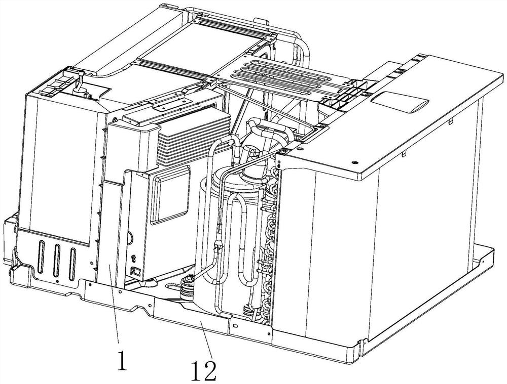
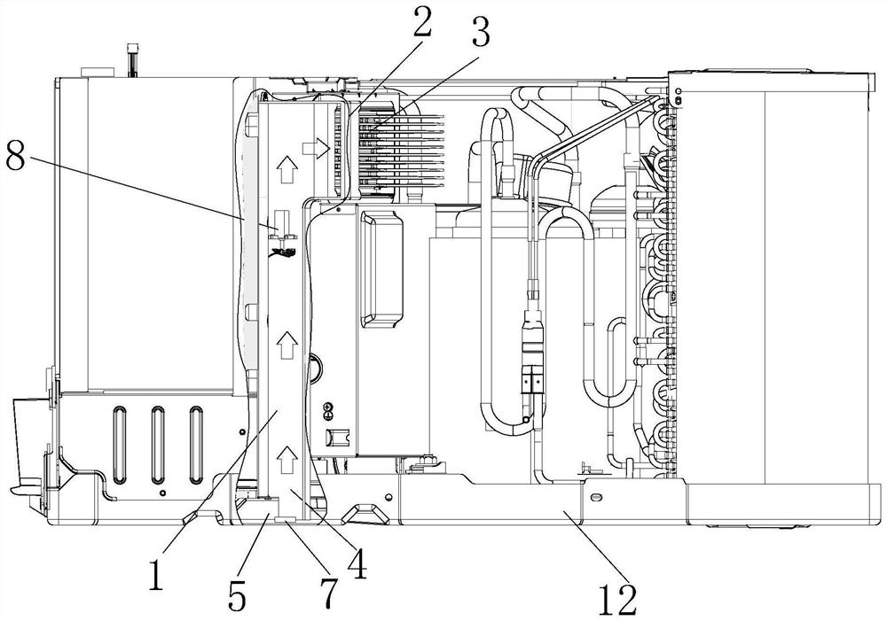
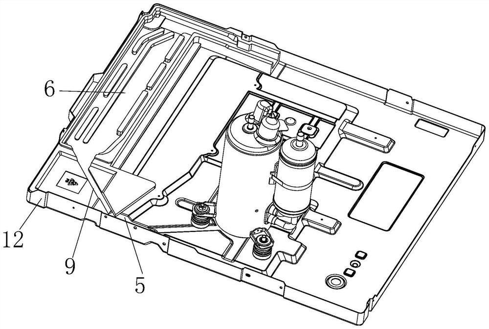
[0038] The auxiliary heat dissipation structure disclosed in this embodiment, figure 1 shown, including the air duct 1 located inside the air conditioner, figure 2 As shown, the air outlet 2 of the air guide duct 1 points to the element to be dissipated 3, and the air inlet 4 of the air guide duct 1 points to the water collecting tank 5, and the water collecting tank 5 is connected to the water receiving tray 6 of the condensed water of the evaporator, figure 2 As shown, the water collecting tank 5 is provided with an atomizer 7, the air guide 1 is provided with an induced draft fan 8, and the exhaust port of the induced draft fan 8 is located at the air outlet 2-1 of the air guide 1 side.

[0039] An induced draft fan 8 is arranged in the air guide duct 1, and the air guide duct 1 can blow the wind generated by the induced draft fan 8 to the surface of the element 3 to be radiated to assist heat dissipation; After the condensed water is atomized, the condensed water is le...

Embodiment 2

[0048] This embodiment discloses an air conditioner, which includes the auxiliary heat dissipation structure of Embodiment 1.

Embodiment 3

[0050] This embodiment discloses the control method of the auxiliary heat dissipation structure in embodiment 1, and the control method includes the following steps,

[0051] S1, detecting the surface temperature T1 of the element 3 to be dissipated,

[0052] S2. When T1≥Ta, start the induced draft fan 8 and detect the water level of the sump 5, if the water level of the sump 5 is lower than the protection value, the atomizer 7 will not start, otherwise start the mist at the same time Converter 7; if T1

[0053] Wherein, when the induced draft fan 8 is turned on, continue to detect the surface temperature T2 of the element 3 to be dissipated, and if T2≥Tb, increase the speed of the induced draft fan 8 , otherwise keep the speed of the induced draft fan 8 .

[0054] Wherein, the surface temperature of the heat dissipation element is detected continuously to obtain T1 and T2 respectively. Continuous detection of the surfac...


PUM


Abstract

The invention relates to the technical field of air conditioners, in particular to an auxiliary heat dissipation structure, an air conditioner and a control method.The auxiliary heat dissipation structure comprises an air guide channel located in the air conditioner, an air outlet of the air guide channel points to a to-be-cooled element, an air inlet of the air guide channel points to a water collecting tank, and the water collecting tank is connected with a water receiving disc of evaporator condensate water; an atomizer is arranged in the water collecting tank, an induced draft fan is arranged in the air guide channel, an air outlet of the induced draft fan is located in one side of an air outlet of the air guide channel, and the auxiliary heat dissipation structure combines the draught fan for blowing air and condensate water to dissipate heat of a to-be-cooled element and supplement and cool the heat dissipation element and has the advantage of being high in heat dissipation stability.

Description

technical field [0001] The invention relates to the technical field of air conditioners, in particular to an auxiliary heat dissipation structure, an air conditioner and a control method. Background technique [0002] In order to reduce the temperature rise of the components in the frequency conversion controller, the frequency conversion controllers all add radiators for auxiliary heat dissipation and cooling. Most of the radiators in the existing frequency conversion controllers are arranged in the air duct of the outdoor unit (side) for air cooling and heat dissipation, or a refrigerant pipe is added on the surface of the radiator to use low-temperature refrigerant for heat dissipation. For example, the frequency conversion controller of the frequency conversion split unit and the frequency conversion window unit is placed on the outdoor unit (side), and the radiator is arranged in the outdoor air duct, and the outdoor air intake is used for heat dissipation. However, wh...

Claims


Application Information

Patent Timeline
Patent Type & Authority Applications(China)
IPC IPC(8): F24F1/06F24F1/16F24F1/38F24F1/42F24F11/64F24F11/871F24F11/88
CPCF24F1/06F24F1/16F24F1/38F24F1/42F24F11/64F24F11/871F24F11/88
Inventor 钟昌原史国桐马傲因梁亚国
Owner GREE ELECTRIC APPLIANCES INC
Why Eureka
Try Eureka