Laser radar angle calibration method and system

A laser radar and calibration method technology, applied in radio wave measurement systems, image analysis, instruments, etc., can solve problems such as difficulty, increased laser radar angle measurement, and complicated angle calibration process, achieving high efficiency and high precision.

Active Publication Date: 2022-04-22
ZVISION TECH CO LTD
View PDF16 Cites 0 Cited by
  • Summary
  • Abstract
  • Description
  • Claims
  • Application Information

AI Technical Summary

Problems solved by technology

However, there are still some deficiencies in the current measurement method for the scanning angle of lidar. For example, the angle calibration process is complicated, and the requirements for the calibration system such as the test site, calibration field, and calibration device are too high, which increases the difficulty of the measurement of the lidar angle.

Method used


Image

  • Laser radar angle calibration method and system
  • Laser radar angle calibration method and system
  • Laser radar angle calibration method and system

Examples


Embodiment Construction

[0045] In the following description, specific details such as specific system structures and technologies are presented for the purpose of illustration rather than limitation, so as to thoroughly understand the embodiments of the present invention. It will be apparent, however, to one skilled in the art that the invention may be practiced in other embodiments without these specific details.

[0046] In order to illustrate the technical solutions of the present invention, specific examples are used below to illustrate.

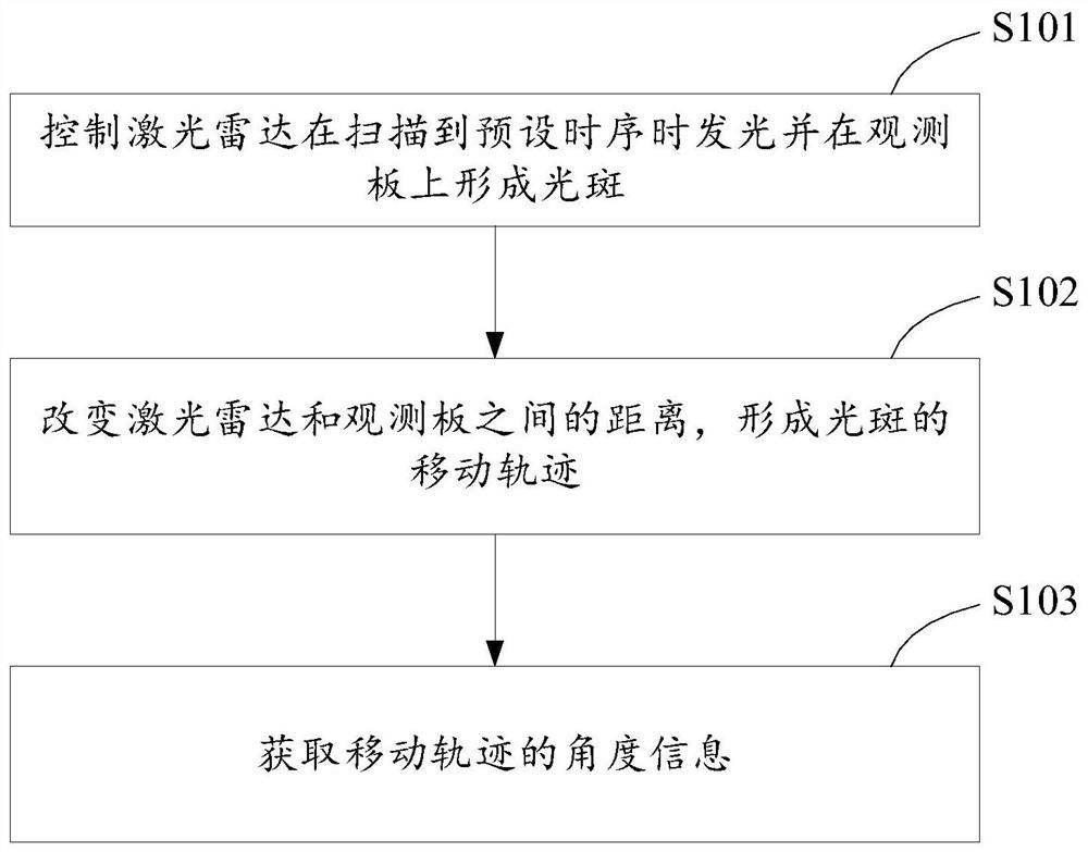
[0047] see figure 1 , which is a schematic flow diagram of an embodiment of the laser radar angle calibration method provided in this embodiment, and is described in detail as follows:

[0048] Step S101, controlling the laser radar to emit light and form a light spot on the observation plate when the preset time sequence is scanned.

[0049] Step S102, changing the distance between the lidar and the observation board to form a moving track of the light spot....


PUM


Abstract

The invention provides a laser radar angle calibration method and system. The method comprises the following steps: controlling a laser radar to emit light when a preset time sequence is scanned, and forming a light spot on an observation plate; changing the distance between the laser radar and the observation plate to form a moving track of the light spot; and acquiring angle information of the moving track. The method solves the problem that a conventional method has too high requirements on a test field, a calibration field, a calibration device and the like, can quickly and reliably calibrate each scanning angle, and is high in precision.

Description

technical field [0001] The invention relates to the technical field of laser radar, in particular to a method and system for calibrating the angle of laser radar. Background technique [0002] As the scanning speed of lidar increases, the density of scanning points becomes higher and higher. However, there are still some shortcomings in the current measurement method for the scanning angle of lidar. For example, the angle calibration process is complicated, and the requirements for calibration systems such as test sites, calibration fields, and calibration devices are too high, which increases the difficulty of measuring the angle of lidar. Contents of the invention [0003] Embodiments of the present invention provide a laser radar angle calibration method and system. [0004] According to the first aspect of the embodiments of the present invention, a method for calibrating the laser radar angle is provided, including: [0005] Controlling the laser radar to emit light...

Claims


Application Information

Patent Timeline
Patent Type & Authority Applications(China)
IPC IPC(8): G01S7/497
CPCG01S7/4972G01S7/497G06T7/13Y02A90/10
Inventor 刘佳尧李艳滨石拓
Owner ZVISION TECH CO LTD
Why Eureka
Try Eureka