A method and system for correcting the take-off and landing direction of an unmanned aerial vehicle
A correction method and unmanned aerial vehicle technology, applied in the control/regulation system, aircraft parts, three-dimensional position/course control, etc., can solve the impact of not considering the wind resistance of the body configuration, reduce the adaptability of the flight environment, and ignore the wind direction parameters and other issues to achieve the effect of reducing the accuracy requirements of heading control, reducing task processing logic, and improving stability
- Summary
- Abstract
- Description
- Claims
- Application Information
AI Technical Summary
Problems solved by technology
Method used
Image
Examples
Embodiment 1
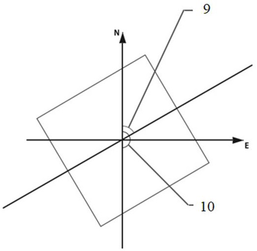
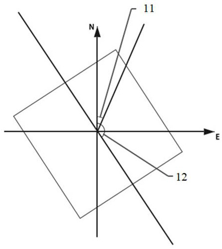
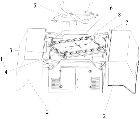
[0094] like Figure 1-Figure 5 As shown, a UAV take-off and landing heading correction method includes a take-off heading correction method and a landing heading correction method. As described with the rotating platform 4 installed on the top of the cabin 3, the rotating platform 4 is used to park the unmanned aerial vehicle 5, and the initial direction of the rotating platform 4 is consistent with the longitudinal position when the unmanned aerial vehicle 5 is parked;
[0095] The method for correcting the takeoff heading includes the following steps:
[0096] Obtain the initial direction α1 angle 9 of the rotating platform 4 and the current wind direction β angle 10 respectively, take the clockwise direction as the direction of angle increase, and the α1 angle 9 and the β angle 10 are both within the range of 0° to 360°;
[0097] Based on the difference θ between the initial direction α1 angle 9 and the current wind direction β angle 10, determine the rotation direction an...
Embodiment 2
[0152] A UAV takeoff and landing heading correction system, such as image 3 As shown, it includes a drone 5 and a machine nest 1, the machine nest 1 includes a cabin 3 and a rotating platform 4 mounted on the top of the cabin 3, the rotating platform 4 is used to park the drone 5, and the no A positioning module is provided on the nose of the man-machine 5, and the take-off and landing heading correction system of the unmanned aerial vehicle 5 further includes: a wind direction acquisition unit, a horizontal distance acquisition unit, a vertical distance acquisition unit and a heading angle acquisition unit;
[0153] The wind direction obtaining unit is used to obtain the wind direction, and is used to adjust the nose position based on the wind direction during the take-off and landing process of the UAV 5;
[0154] The rotary platform 4 is used to rotate based on the difference θ between the initial direction α1 angle 9 of the rotary platform 4 and the current wind direction...
Embodiment 3
[0160] Follow the above technical solutions, such as Figure 1-Figure 5 As shown, a UAV take-off and landing heading correction method includes a take-off heading correction method and a landing heading correction method, including a machine nest 1 and a machine nest top cover 2, and the machine nest 1 includes a cabin body 3 and is installed in the cabin body. 3 The rotating platform 4 on the top, the drone 5 is parked on the top of the rotating platform 4;
[0161] The method for correcting the takeoff heading includes the following steps:
[0162] Step 1: Open the top cover 2 of the machine nest and obtain the initial direction of the rotating platform 4, α1, 9 and wind direction information, 10, β, north and east. The initial direction of the rotating platform 4 is consistent with the longitudinal position of the UAV 5. The clockwise direction is the direction in which the angle increases, and the ranges of α1 angle 9 and β angle 10 are both 0° to 360°;
[0163] specific...
PUM
 Abstract
Description
Claims
Application Information
 - R&D
- Intellectual Property
- Life Sciences
- Materials
- Tech Scout
- Unparalleled Data Quality
- Higher Quality Content
- 60% Fewer Hallucinations
Browse by: Latest US Patents, China's latest patents, Technical Efficacy Thesaurus, Application Domain, Technology Topic, Popular Technical Reports.
© 2025 PatSnap. All rights reserved.Legal|Privacy policy|Modern Slavery Act Transparency Statement|Sitemap|About US| Contact US: help@patsnap.com


