Method, equipment and medium for dynamic matching of overlapping grid size based on cell cutting

A grid size and dynamic matching technology, applied in the field of computational fluid dynamics, can solve problems such as inefficient grid unit layout, difficulty in achieving size matching, and exceeding the limit of computing resources, so as to improve grid utilization efficiency and ensure interpolation accuracy , the effect of improving the efficiency of numerical simulation

Active Publication Date: 2022-06-07
CALCULATION AERODYNAMICS INST CHINA AERODYNAMICS RES & DEV CENT
View PDF10 Cites 0 Cited by
  • Summary
  • Abstract
  • Description
  • Claims
  • Application Information

AI Technical Summary

Problems solved by technology

This method can only refine the grid to a certain extent, the layout of grid cells is inefficient, and it is difficult to achieve size matching on the entire trajectory
What's more serious is that for applications with large relative displacements, enlarging the grid in the entire trajectory area will lead to a huge increase in the total number of grid cells, even exceeding the limit of computing resources

Method used


Image

  • Method, equipment and medium for dynamic matching of overlapping grid size based on cell cutting
  • Method, equipment and medium for dynamic matching of overlapping grid size based on cell cutting
  • Method, equipment and medium for dynamic matching of overlapping grid size based on cell cutting

Examples


Embodiment 1

[0098] Example 1: as Figure 10 As shown in the figure, a method for dynamic matching of overlapping grid sizes based on element cutting is characterized in that, comprising the steps of:

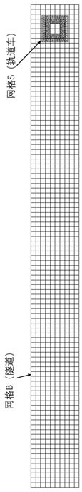
[0099] S1, consider two sets of grid S and grid B overlapping each other at any time t, the cell size of grid B is larger than the cell size of grid S, and the grid area of ​​grid B wraps grid S, grid S The area enclosed by the outer boundary is the overlapping area Ω; the grid cell sets IN and OUT that enter and leave the overlapping area Ω in grid B are determined according to the positional relationship of the grid cells, and the grid cells that intersect the boundary of the overlapping area are also added to the set IN;

[0100] S2, determine the cutting unit list P;

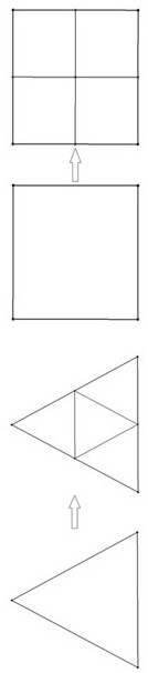
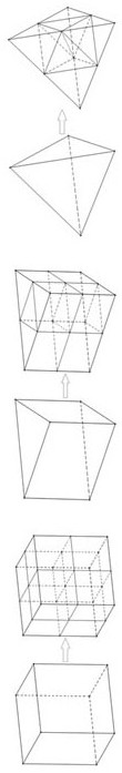
[0101] S3, cutting grid cells;

[0102] S4, restore the grid cell size;

[0103] S5, proceed to the next moment t +1, repeat step S1 to step S4, complete t +1 moment grid cell size match.

Embodiment 2

[0104] Embodiment 2: Based on Embodiment 1, in step S1, the grid unit positional relationship is determined by the following criterion 1:

[0105] Criterion 1:

[0106] ① The grid cells are located in the overlapping region Ω: if and only if all the vertices of the grid cells are located in the overlapping region Ω;

[0107] ②The grid unit is outside the overlapping area Ω: if and only if all the vertices of the grid unit are outside the overlapping area Ω;

[0108] ③ The grid cell intersects the boundary of the overlapping region Ω: the grid cell is not located in the region Ω, nor is it located outside the overlapping region Ω.

Embodiment 3

[0109] Embodiment 3: Based on Embodiment 1, in step S1, in a three-dimensional case, the positional relationship between the vertex of the mesh unit and the overlapping area Ω is determined by using the ray method.


PUM


Abstract

The invention discloses a method, device and medium for dynamic matching of overlapping grid sizes based on cell cutting, belonging to the field of computational fluid dynamics, comprising the step of: S1, judging the entry and exit of the overlapping area Ω in grid B according to the positional relationship of grid cells The grid unit sets IN and OUT of the grid unit, in which the grid unit intersecting the boundary of the overlapping area are also added to the set IN; S2, determine the cutting unit list P; S3, cut the grid unit; S4, restore the size of the grid unit; S5, carry out to the next moment t +1, repeat step S1 to step S4, complete t +1 for moment grid cell size matching. The invention improves grid utilization efficiency, realizes dynamic matching of overlapping grid sizes, not only ensures interpolation accuracy, but also controls the number of grid units to the greatest extent, and efficiently solves the problem of overlapping grid size matching.

Description

technical field [0001] The invention relates to the field of computational fluid dynamics, and more particularly, to a method for dynamic matching of overlapping grid sizes based on element cutting. Background technique [0002] Fluid mechanics often needs to deal with the dynamic interaction of aerodynamics caused by the relative motion of multiple components, such as high-speed trains entering and exiting tunnels and aircraft launching missiles. In computational fluid dynamics, overlapping grid technology is often used to realize the real-time movement of computational grids following components, and the interaction between components is transmitted through the interpolation of the flow field between grids. In order to ensure the accuracy of flow field interpolation between grids as much as possible, the grid cells that overlap each other must be matched in size (close in size). The current commonly used method is to first estimate the motion trajectory, and then pre-refi...

Claims


Application Information

Patent Timeline
Patent Type & Authority Patents(China)
IPC IPC(8): G06F30/28G06F30/23G06T17/20G06F111/10G06F113/08G06F119/14
CPCG06F30/28G06F30/23G06T17/20G06F2113/08G06F2119/14G06F2111/10Y02T90/00
Inventor 唐静周乃春张耀冰吴晓军崔鹏程陈江涛付云峰张建李彬龚小权周桂宇李欢周泽堃
Owner CALCULATION AERODYNAMICS INST CHINA AERODYNAMICS RES & DEV CENT
Why Eureka
Try Eureka