Supercharge Your Innovation With Domain-Expert AI Agents!

Magnet-supported vertical contact separation mode nanogenerator

A nanogenerator and contact separation technology, applied in induction generators, friction generators, etc., can solve the problems of low elastic structure stability, structural wear, fatigue failure, etc., and achieve the speed of separation movement and improve stability. Effect

Pending Publication Date: 2022-04-22
TSINGHUA UNIV
View PDF0 Cites 0 Cited by
  • Summary
  • Abstract
  • Description
  • Claims
  • Application Information

AI Technical Summary

Problems solved by technology

[0005] 1) The elastic deformation recovery of the elastic structure is relatively slow, so the electrical signal output response during the electrode separation process will be slower; 2) The elastic deformation has the risk of structural wear and fatigue failure, for example, if the external force is too large or the number of deformations is too large, the elastic The structure will fail, resulting in low stability of the elastic structure

Method used


Image

  • Magnet-supported vertical contact separation mode nanogenerator
  • Magnet-supported vertical contact separation mode nanogenerator
  • Magnet-supported vertical contact separation mode nanogenerator

Examples


Embodiment 1

[0038] The magnet-supported vertical contact-separation mode nanogenerator includes a moving plate unit 1 and a fixed plate unit 2 stacked according to a set distance, and both the fixed plate unit and the moving plate unit include a pole plate, a The magnet and the metal electrode layer laid on the pole plate; wherein, the metal electrode layer of the moving plate unit is electrode one, and the metal electrode layer of the fixed plate unit is electrode two; electrode one and electrode two form the output electrode of the generator; An electret dielectric layer or a friction layer is laid on the first metal electrode layer; wherein, the first metal electrode layer is laid on the opposite surface of the fixed plate unit and the moving plate unit; the magnet of the fixed plate unit and the The magnets of the movable plate unit are arranged to repel each other to generate a repulsive force for separating the vertically contacted fixed plate unit from the movable plate unit, so tha...

Embodiment 2

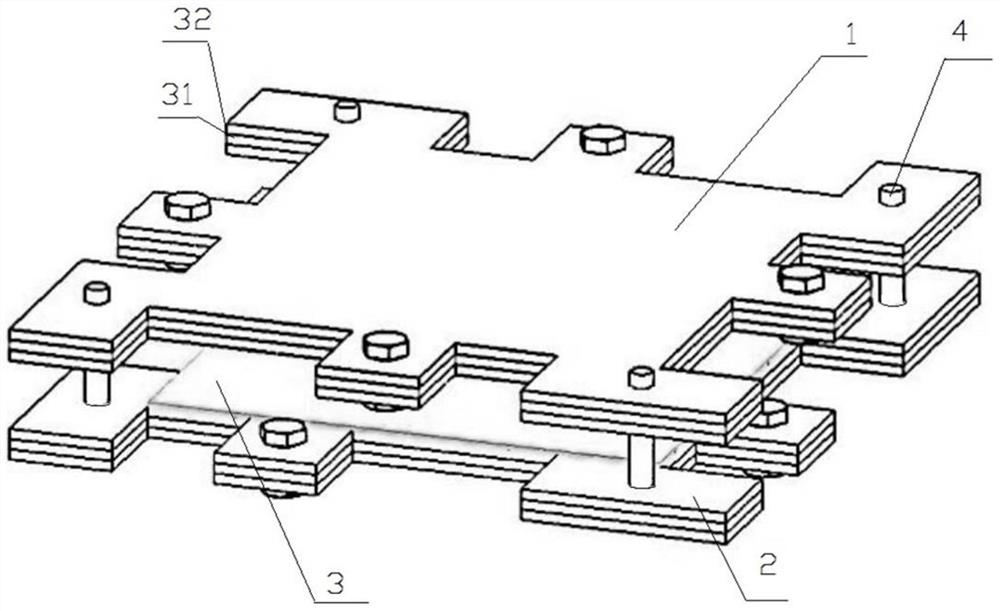
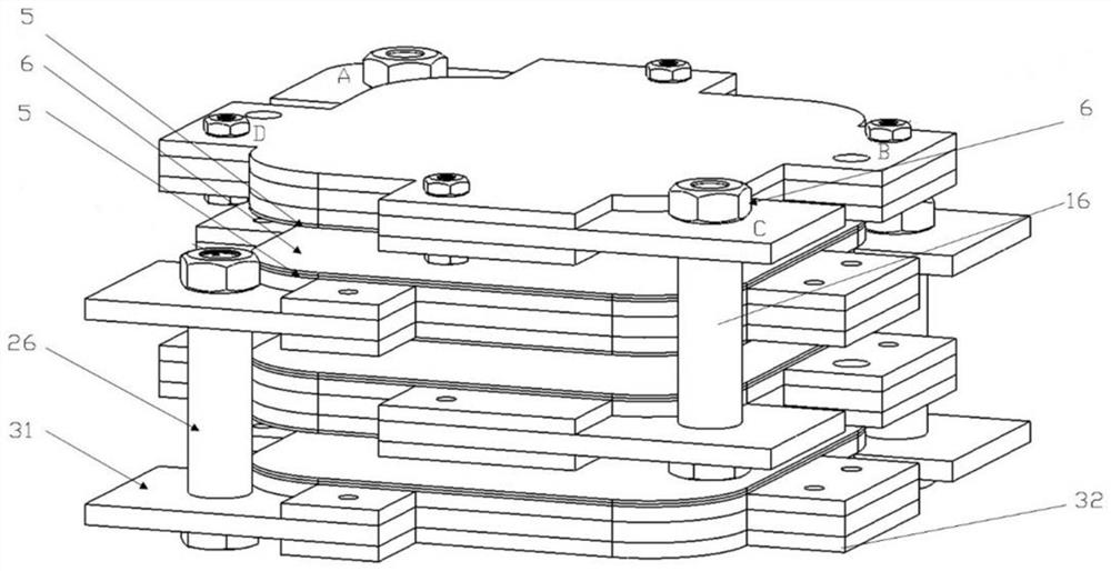
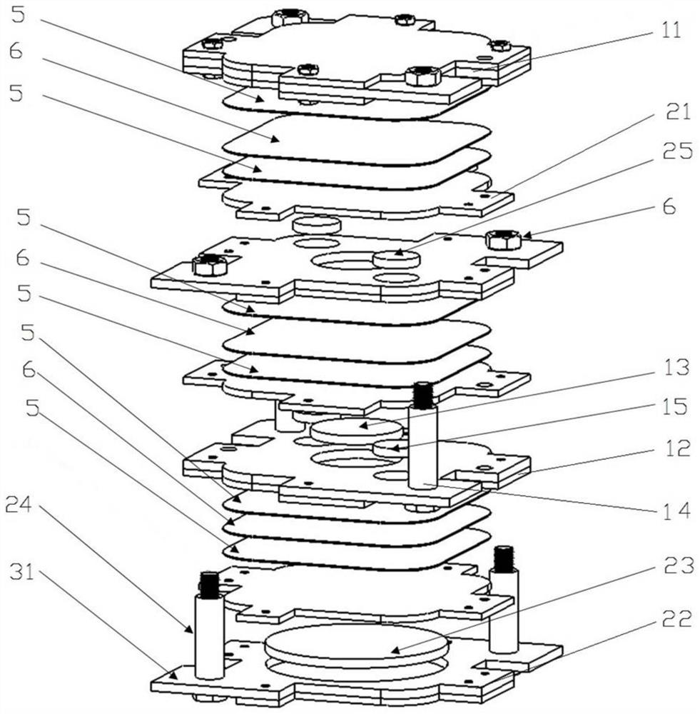
[0048] Figure 2 ~ Figure 4 The overall structure of the magnet-supported vertical contact-separation mode nanogenerator provided by Example 2 of the present invention is described. in, figure 2 Schematic diagram of the structure of the magnet-supported vertical contact-separation mode nanogenerator provided in Example 2 of the present invention, image 3 An exploded view of the structure of the magnet-supported vertical contact-separation mode nanogenerator provided in Example 2 of the present invention; Figure 4 A side view of the structure of the magnet-supported vertical contact-separation mode nanogenerator provided in Example 2 of the present invention.

[0049] refer to Figure 2 ~ Figure 4 As shown, the number of pole plates of the fixed pole plate unit 1 and the movable pole plate unit 2 is 2 respectively; the movable pole plate unit 1 includes a relatively fixed pole plate 11 and a pole plate 3 12 according to a set distance; the fixed pole plate The unit 2 inc...


PUM


Abstract

The invention relates to the technical field of nano-generators, and provides a magnet-supported vertical contact separation mode nano-generator, which can improve the equipment stability and accelerate the separation movement speed of the generator by using the repulsive force between magnets as the separation restoring force. The repulsive force and the distance between the magnets are in a non-linear relationship, and when the two magnets are close enough, the repulsive force, namely the separation restoring force, is greatly increased, so that the separation movement speed of the generator is further accelerated; in addition, introduction of an elastic structure is avoided, magnet attraction force is used as correction restoring force in separation motion of the generator, it is guaranteed that the movable pole plate group returns to a set position after being separated every time, and then the stability of the generator is improved.

Description

technical field [0001] The invention relates to the technical field of nanogenerators, in particular to a nanogenerator in a vertical contact separation mode supported by magnets. Background technique [0002] With the further development and realization of 5G technology and Internet of Things technology, a huge number of distributed sensor networks are required to meet people's needs for intelligence, informatization, and modernization. However, how to supply power to the widely distributed and large number of sensor networks has become an urgent problem to be solved. The traditional battery power supply is not friendly to the environment, and it carries limited energy and needs to be replaced regularly, which has the disadvantages of increasing time cost and economic cost. [0003] An alternative to batteries is to harvest energy from the environment to power sensors. Among them, triboelectric nanogenerators and electret generators have attracted a worldwide research boom...

Claims


Application Information

Patent Timeline
Patent Type & Authority Applications(China)
IPC IPC(8): H02N1/04H02N1/08
CPCH02N1/04H02N1/08
Inventor 唐飞杨爽爽楚尧董伉伉王晓浩
Owner TSINGHUA UNIV
Features
  • R&D
  • Intellectual Property
  • Life Sciences
  • Materials
  • Tech Scout
  • Unparalleled Data Quality
  • Higher Quality Content
  • 60% Fewer Hallucinations
Learn More