
MEMS microphone structure

A microphone and one-sided technology, applied in the field of microphones, can solve problems such as the deterioration of low-frequency characteristics of MEMS microphones, and achieve the effect of easy vibration and improvement of low-frequency characteristics

Pending Publication Date: 2022-04-22
瑶芯微电子科技(上海)有限公司
View PDF0 Cites 0 Cited by
  • Summary
  • Abstract
  • Description
  • Claims
  • Application Information

AI Technical Summary

Problems solved by technology

[0003] In view of the above-mentioned shortcoming of prior art, the object of the present invention is to provide a kind of MEMS microphone structure, be used to solve the problem of the low-frequency characteristic deterioration of MEMS microphone in the prior art

Method used


Image

  • MEMS microphone structure
  • MEMS microphone structure
  • MEMS microphone structure

Examples


Embodiment Construction

[0044] Embodiments of the present invention are described below through specific examples, and those skilled in the art can easily understand other advantages and effects of the present invention from the content disclosed in this specification. The present invention can also be implemented or applied through other different specific implementation modes, and various modifications or changes can be made to the details in this specification based on different viewpoints and applications without departing from the spirit of the present invention.

[0045] see Figure 1 to Figure 5 . It should be noted that the diagrams provided in this embodiment are only schematically illustrating the basic idea of ​​the present invention, and only the components related to the present invention are shown in the diagrams rather than the number, shape and shape of the components in actual implementation. Dimensional drawing, the type, quantity and proportion of each component can be changed arb...


PUM


Abstract

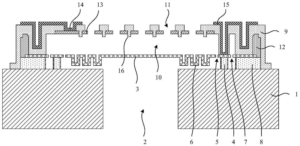
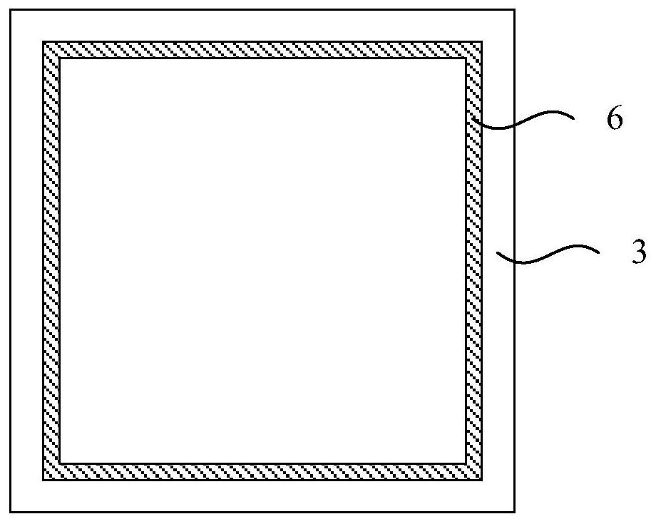
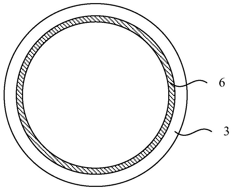
The invention provides an MEMS microphone structure, which comprises a substrate, a cavity, a vibrating diaphragm, an inner bracket and an air leakage hole, and is characterized in that the cavity is located in the substrate and vertically penetrates through the substrate; the vibrating diaphragm is suspended above the cavity; the inner bracket is connected between the vibrating diaphragm and the substrate; the air leakage hole is located in the vibrating diaphragm and vertically penetrates through the vibrating diaphragm, and the distance between the air leakage hole and the center of the vibrating diaphragm is smaller than that between the inner support and the center of the vibrating diaphragm; the diaphragm comprises a folding area, and the distance between the folding area and the center of the diaphragm is smaller than the distance between the deflation hole and the center of the diaphragm. The diaphragm of the MEMS microphone structure comprises the folding area serving as an acoustic resistance increasing device, the folding area is located between the air leakage hole and the center of the diaphragm, and when the MEMS microphone receives low-frequency sound wave vibration (acting on the diaphragm), the folding area can increase the acoustic resistance of the low-frequency sound wave on a flowing path of the air leakage hole, so that the sound resistance of the low-frequency sound wave is increased. Therefore, the low-frequency characteristic of the MEMS microphone is effectively improved. In addition, the folding area enables the vibrating diaphragm to vibrate more easily.

Description

technical field [0001] The invention belongs to the technical field of microphones and relates to a MEMS microphone structure. Background technique [0002] Today's smartphones and smart speakers use microphones made with MEMS (Micro-Electro-Mechanical System) technology. This microphone has the characteristics of small size, low power consumption, excellent performance, good consistency, and easy assembly. The core component of a MEMS microphone is a flexible membrane that vibrates back and forth. In the event that such a microphone is manufactured or dropped during use, the flexible diaphragm may be damaged by the impact of high air pressure. The usual solution is to provide a vent hole on the diaphragm, so that when the diaphragm is subjected to high air pressure impact, the air can be released through the vent hole, thereby reducing the pressure that the diaphragm must bear. However, in the MEMS microphone with the vent hole structure, when the low-frequency sound wav...

Claims


Application Information

Patent Timeline
Patent Type & Authority Applications(China)
IPC IPC(8): H04R19/00H04R19/04
CPCH04R19/005H04R19/04H04R2201/003
Inventor 王青松
Owner 瑶芯微电子科技(上海)有限公司
Learn More