Pre-amplification electric circuit used for infrared alarm

A preamplifier circuit and alarm technology, which is applied in the direction of improving the amplifier to reduce the impact of noise, can solve the problems of poor low-frequency characteristics and high noise of the preamplifier circuit, and achieve good low-frequency characteristics, noise suppression, and strong anti-noise interference Effect

Inactive Publication Date: 2015-05-20
SCISHINE SICHUAN
View PDF0 Cites 2 Cited by
  • Summary
  • Abstract
  • Description
  • Claims
  • Application Information

AI Technical Summary

Problems solved by technology

At present, the preamplifier circuit of the low-priced infrared alarm has poor low-frequency characteristics and high noise

Method used


Image

  • Pre-amplification electric circuit used for infrared alarm

Examples


Embodiment Construction

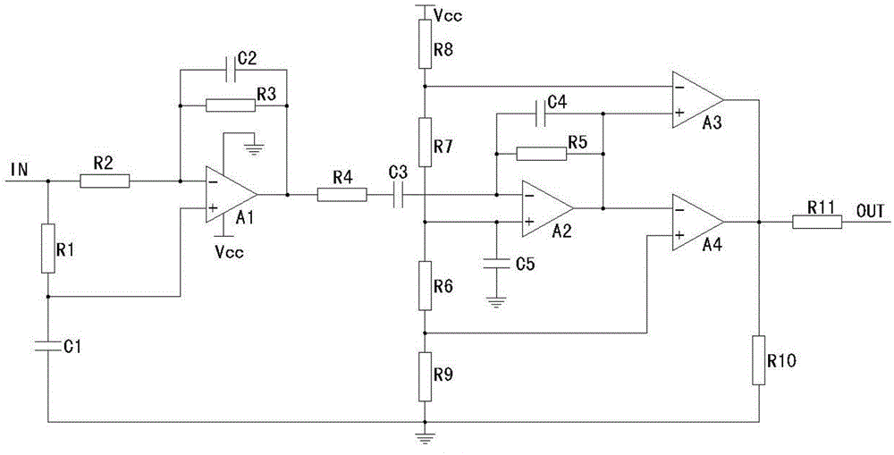
[0009] The present invention will be further described below in conjunction with accompanying drawing:

[0010] Such as figure 1 As shown, the preamplifier circuit for the infrared alarm described in the present invention includes a first resistor R1, a second resistor R2, a third resistor R3, a fourth resistor R4, a fifth resistor R5, a sixth resistor R6, a Seventh resistor R7, eighth resistor R8, ninth resistor R9, tenth resistor R10, eleventh resistor R11, first capacitor C1, second capacitor C2, third capacitor C3, fourth capacitor C4, fifth capacitor C5, The first operational amplifier A1, the second operational amplifier A2, the third operational amplifier A3, the fourth operational amplifier A4 and a DC power supply (not shown in the figure), the first terminal of the first resistor R1 and the first terminal of the second resistor R2 Terminal connected and used as the signal input terminal IN of the preamplifier circuit, the second terminal of the first resistor R1 is ...


PUM


Abstract

The invention discloses a pre-amplification electric circuit used for an infrared alarm. The pre-amplification electric circuit used for the infrared alarm comprises a first resistor, a second resistor, a third resistor, a fourth resistor, a fifth resistor, a sixth resistor, a seventh resistor, an eighth resistor, a ninth resistor, a tenth resistor, an eleventh resistor, a first capacitor, a second capacitor, a third capacitor, a fourth capacitor, a fifth capacitor, a first operational amplifier, a second operational amplifier, a third operational amplifier, a fourth operational amplifier and a direct-current power supply, wherein the second resistor, the third resistor, the second capacitor and the first operational amplifier form a first-level amplification circuit, the fourth resistor, the fifth resistor, the sixth resistor, the seventh resistor, the third capacitor, the fourth capacitor and the second operational amplifier form a second-level amplification circuit, and the eighth resistor, the ninth resistor, the tenth resistor, the third operational amplifier and the fourth operational amplifier form a voltage comparison circuit. The pre-amplification electric circuit used for the infrared alarm is good in low-frequency characteristic and is high in amplification gain for low-frequency weak signals output by an infrared detector. The pre-amplification electric circuit can effectively restrain noise, is high in anti-noise-interference ability, is simple in structure and uses few components.

Description

technical field [0001] The invention relates to a preamplifier circuit for an infrared alarm, in particular to a high-gain and low-noise preamplifier circuit for an infrared alarm. Background technique [0002] The object detected by the infrared detector is an infrared output pulse signal. The pulse signal is amplified and filtered, and compared with the reference voltage by the voltage operational amplifier. When the output signal reaches a certain value, the alarm will send out an alarm. Among them, the pre-amplification circuit of the infrared alarm is an important part. At present, the preamplifier circuit of the low-priced infrared alarm has poor low-frequency characteristics and high noise. Contents of the invention [0003] The object of the present invention is to provide a high-gain and low-noise preamplifier circuit for infrared alarms in order to solve the above problems. [0004] The present invention achieves the above object through the following technical...

Claims


Application Information

Patent Timeline
Patent Type & Authority Applications(China)
IPC IPC(8): H03F1/26
Inventor 张红雨
Owner SCISHINE SICHUAN
Why Eureka
Try Eureka