Single-blade wheel

A single-blade and impeller technology, applied in the direction of liquid fuel engines, machines/engines, mechanical equipment, etc., can solve the problems of expensive manufacturing, achieve the effects of reducing vibration characteristics, improving efficiency and operating reliability, and reducing noise emissions

Pending Publication Date: 2022-04-22
KSB AG
View PDF0 Cites 0 Cited by
  • Summary
  • Abstract
  • Description
  • Claims
  • Application Information

AI Technical Summary

Problems solved by technology

However, the single-blade wheel should be formed from metallic material, making it more expensive to manufacture with cavities

Method used


Image

  • Single-blade wheel
  • Single-blade wheel
  • Single-blade wheel

Examples


Embodiment Construction

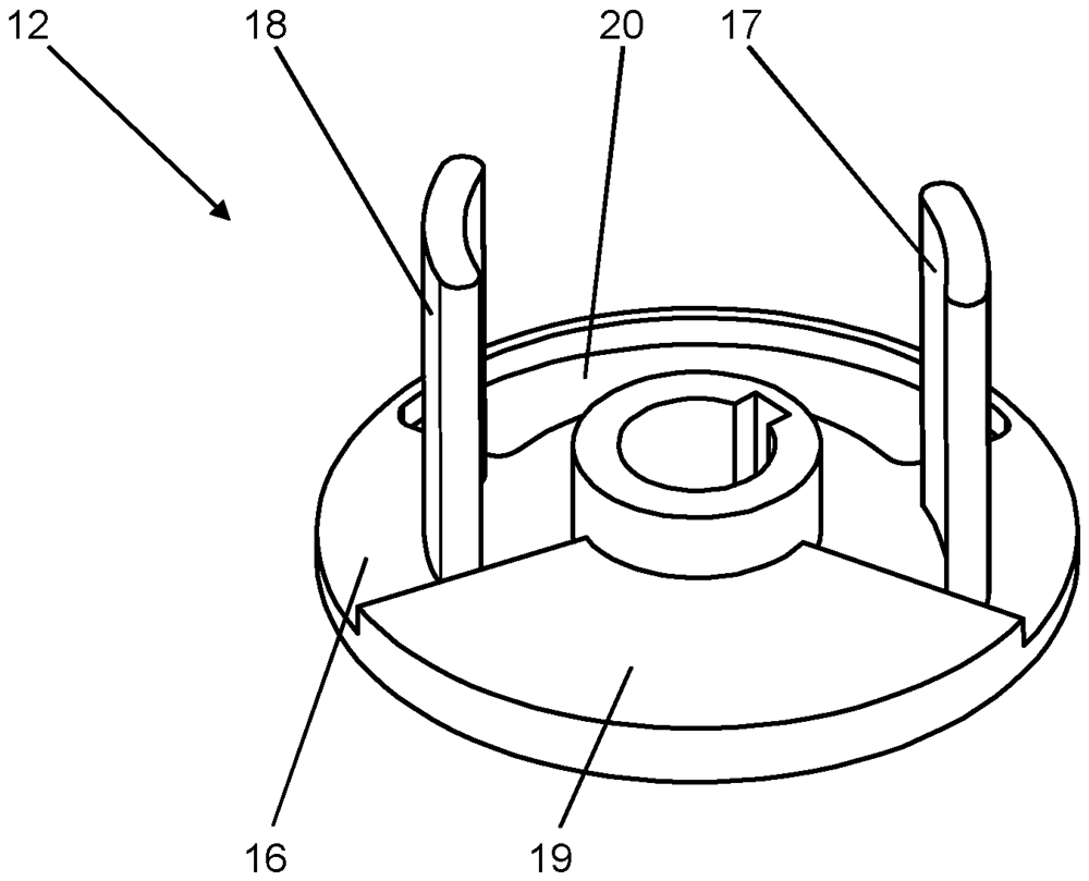
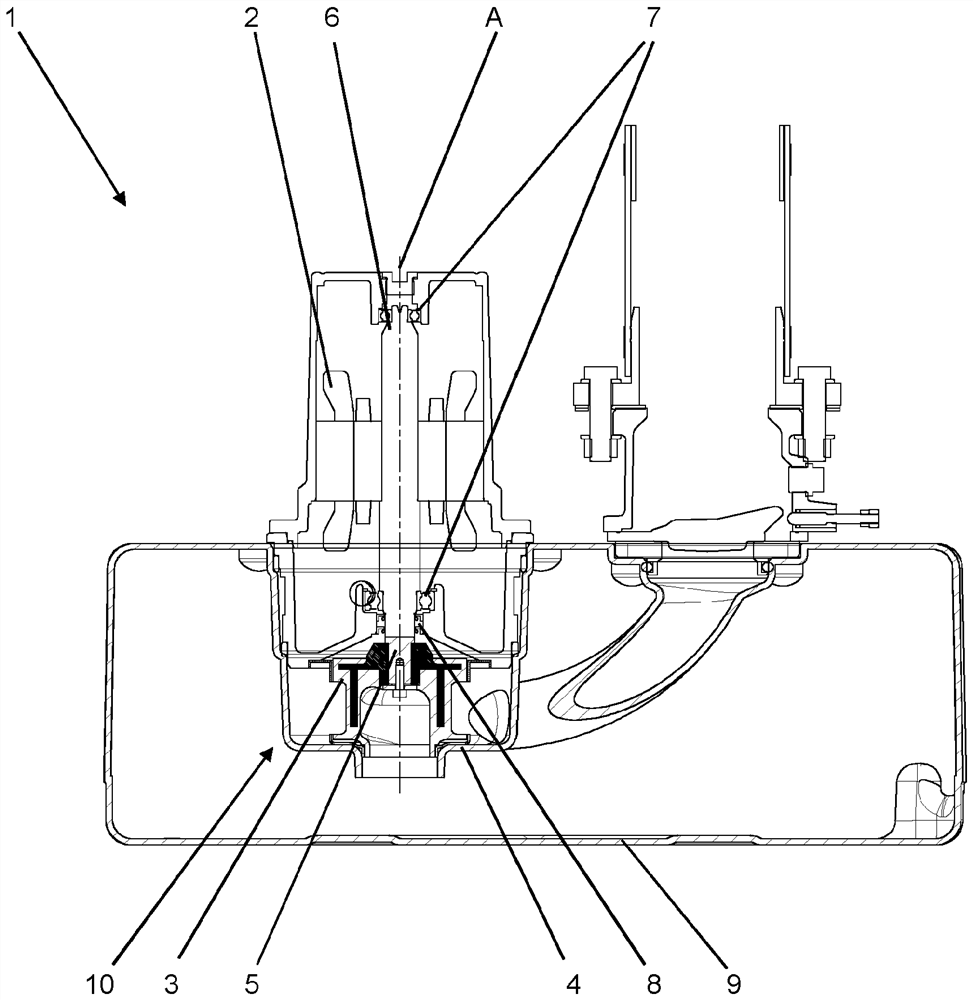
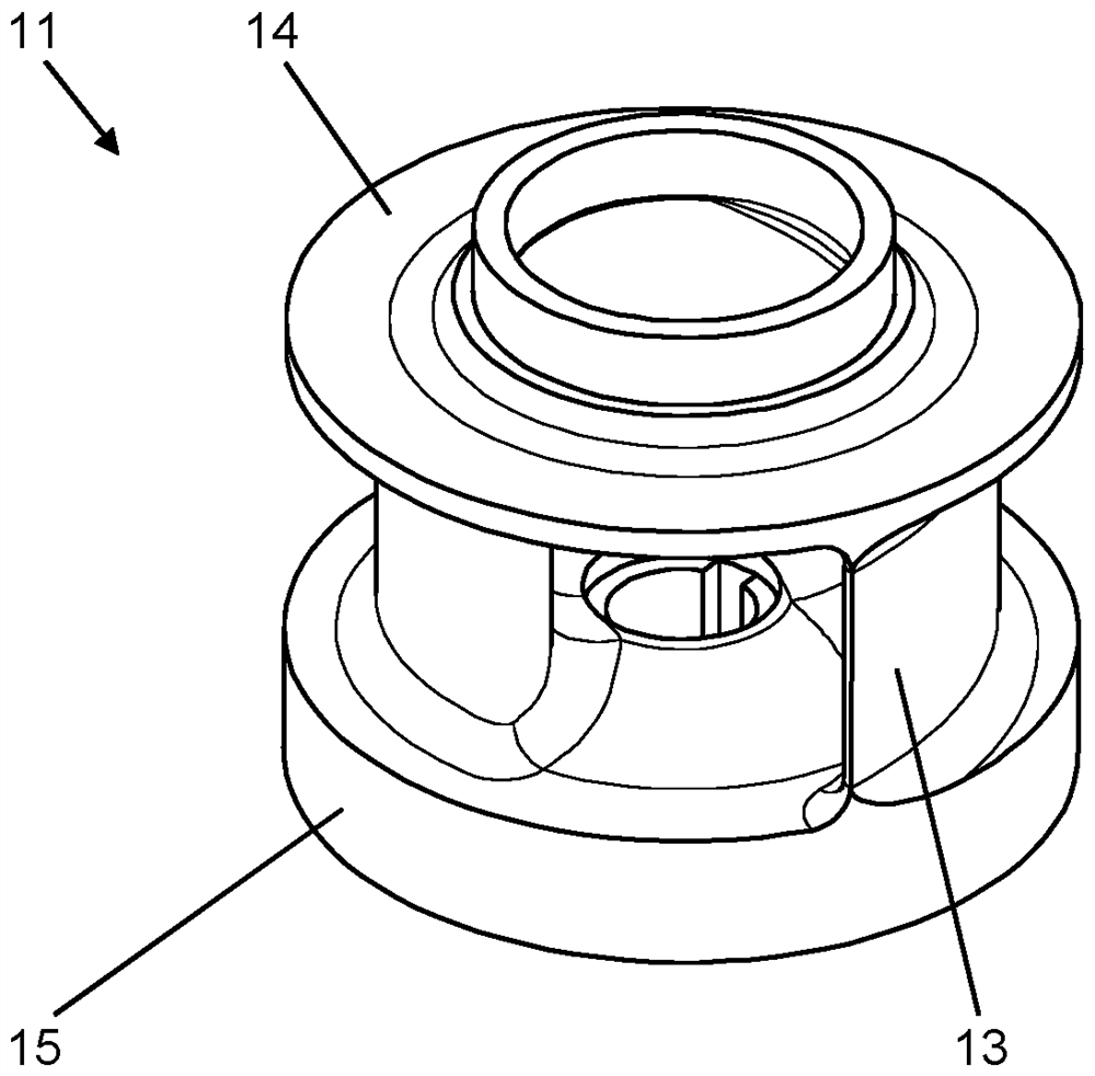
[0021] figure 1 A pump arrangement is shown having a pump 1 with a drive motor 2 and a single-blade wheel 3 , wherein the single-blade wheel 3 is arranged inside a pump housing 4 . The single-blade wheel 3 is fastened to the motor shaft 6 of the drive motor 2 via the impeller shaft 5 , which rotates about the axis A of rotation. In the illustration shown, the impeller shaft 5 and the motor shaft 6 are formed in one piece. As an alternative, the impeller shaft 5 and the motor shaft 6 can be connected to each other by a joint element.

[0022] A threaded connection is provided as a means of fixing the single-blade wheel 3 on the impeller shaft 5 , and the torque transmission takes place via rib keys. In addition, the motor shaft 6 is mounted via a rolling bearing 7 and is sealed against the single-blade wheel 3 with a seal 8 . In the exemplary embodiment shown, the pump device is arranged on a container 9 which forms the pump housing 4 in a region 10 . However, the single-bl...


PUM

PropertyMeasurementUnit
densityaaaaaaaaaa

Abstract

The invention relates to a single-blade wheel (3) for a pump for conveying a liquid mixed with a solid mixture, comprising a wheel body (11) in which blades (13) are arranged between a first cover disc (14) and a second cover disc (15), the thickness of the wall of the blades (13) varying over the extent thereof, and wherein a channel is formed between the blade (13) and the cover disc (14, 15). According to the invention, a support body (12) is arranged at least partially in the impeller body (11), said support body having an increased density relative to the impeller body (11).

Description

technical field [0001] The invention relates to a single-blade wheel for a pump, in particular a centrifugal pump, having an impeller body in which blades are arranged between a first suction-side cover disk and a pressure-side second cover disk. , wherein the thickness of the wall of the vane varies over its extent, and wherein a channel is formed between the vane and the cover disk. Background technique [0002] Such a single-blade wheel is usually used if a mixture of liquids mixed with solids is to be conveyed. In particular, this is sewage water with a coarse-grained and long-fibrous component. Such single-blade wheels are characterized in that, in contrast to other types of impellers, only one blade is provided through which the liquid is conveyed. The vanes are designed in such a way that they form channels through which liquid can flow starting from the suction opening. Such a single-blade wheel can be designed to be very solid and low-wear, so that reliable and a...

Claims


Application Information

Patent Timeline
Patent Type & Authority Applications(China)
IPC IPC(8): F04D29/22F04D29/02F04D29/66
CPCF04D29/225F04D29/026F04D29/669F05D2300/522F05D2300/43F05D2300/44F05D2300/111
Inventor A·克里斯特C·耶格R·维策尔
Owner KSB AG
Why Eureka
Try Eureka