Cold compress nursing equipment for outer epidermis of leg burn patient

An outer skin and patient technology, which is applied in the directions of heating appliances for therapeutic treatment, cooling appliances for therapeutic treatment, contraceptive appliances, etc., can solve the problems of inconvenient handling of ice cubes and manual operation, and achieves improved convenience and prevention of excessive speed. The effect of melting and saving electricity

Pending Publication Date: 2022-04-26
付德为
View PDF0 Cites 0 Cited by
  • Summary
  • Abstract
  • Description
  • Claims
  • Application Information

AI Technical Summary

Problems solved by technology

[0005] In order to overcome the disadvantages of manual operation and inconvenient handling of ice cubes in existing nursing equipment, the purpose of the present invention is to provide a cold compress for the outer skin of patients with leg burns that is easy to clean and can avoid errors caused by manual operation through automatic operation. nursing equipment

Method used


Image

  • Cold compress nursing equipment for outer epidermis of leg burn patient
  • Cold compress nursing equipment for outer epidermis of leg burn patient
  • Cold compress nursing equipment for outer epidermis of leg burn patient

Examples


Embodiment 1

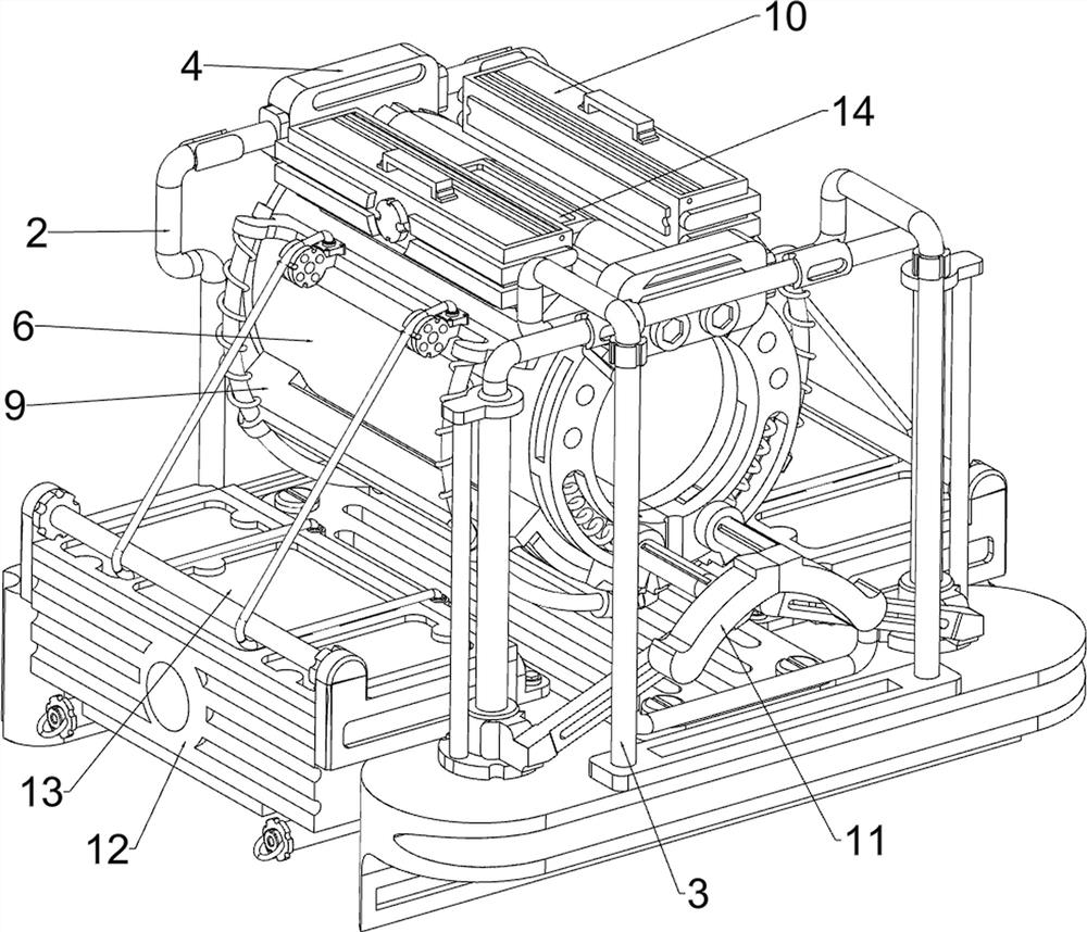
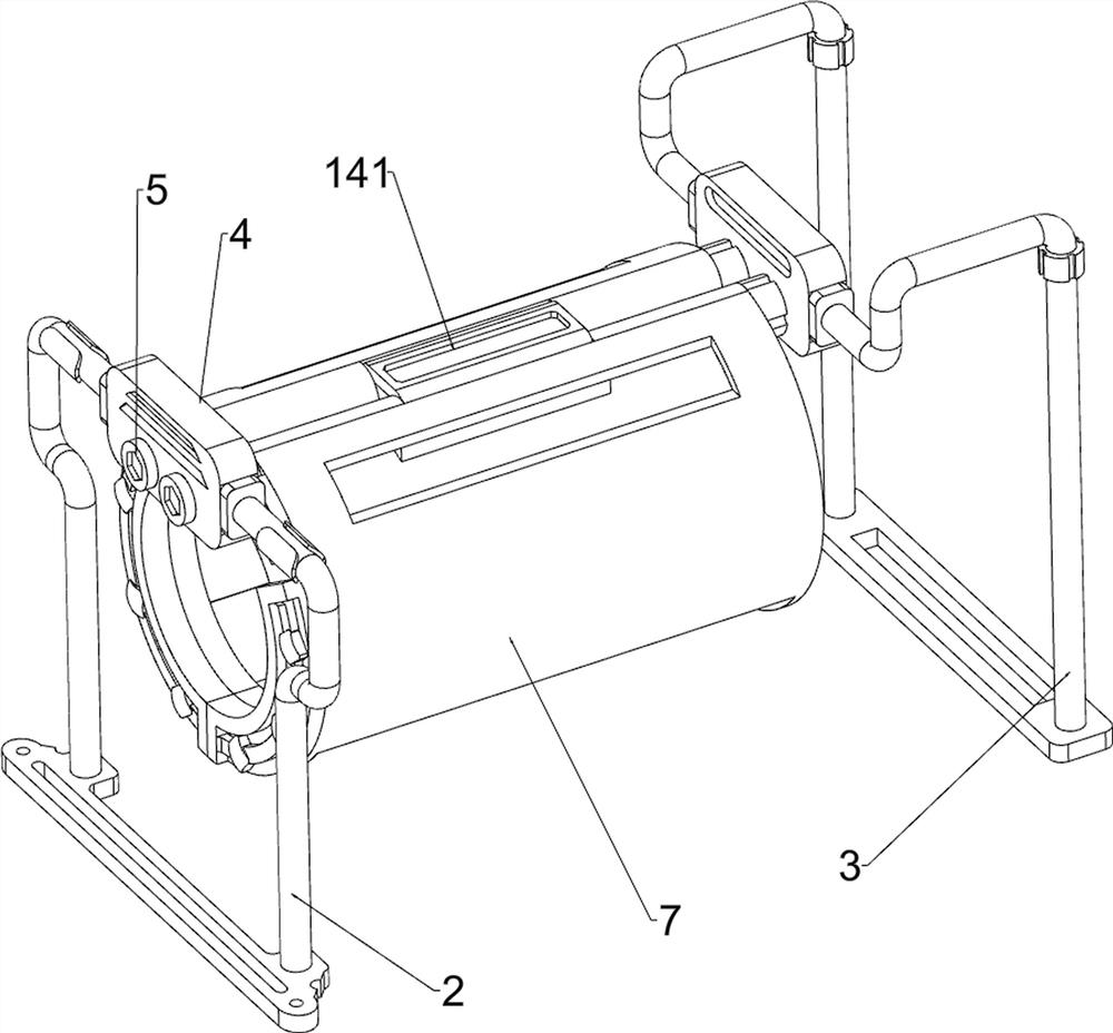
[0042] A kind of cold compress care equipment for the outer skin of patients with leg burns, which is used in Figure 1-5 As shown in , it includes a base 1, a first mounting frame 2, a second mounting frame 3, a support block 4, a rotating shaft 5, a scroll spring 6, a housing 7, a plastic cloth 8, a blocking mechanism 9, a feeding mechanism 10 and The transmission mechanism 11, the front side of the top of the base 1 is connected with the first mounting frame 2 by means of screw connection, the rear side of the top of the base 1 is connected with the second mounting frame 3 by means of screw connection, the first mounting frame 2 and the second mounting frame The upper side of 3 is welded with supporting blocks 4, and the two supporting blocks 4 are symmetrically rotated left and right and are provided with rotating shafts 5, and the two rotating shafts 5 on the same side in the longitudinal direction are all connected with a joint that can limit the position of the patient's...

Embodiment 2

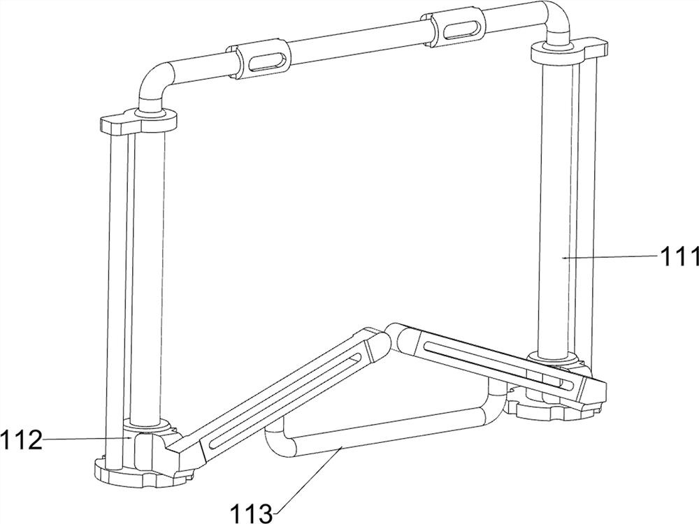
[0048] On the basis of Example 1, in figure 1 , figure 2 , Figure 14 and Figure 15 As shown in , it also includes a storage mechanism 12. The storage mechanism 12 includes a storage box 121, a connecting pipe 122 and a threaded block 123. The left and right sides of the base 1 are connected with a storage box 121 for storing ice cubes by bolts. The front and back of the bottom of the box 121 are symmetrically provided with connecting pipes 122 to facilitate the discharge of ice water, and the sides of the four connecting pipes 122 away from each other are all connected with threaded blocks 123 by means of threaded connections.

[0049] After the patient's cold compress is completed, the electric slide rail 111 works so that the connecting frame 117 pushes the sliding plate 93 to slide upwards to open, and the ice cubes in the housing 7 will fall into the storage box 121 through the chute, and the storage box 121 can store used Because some of the ice cubes will melt duri...


PUM


Abstract

The invention relates to nursing equipment, in particular to cold compress nursing equipment for the outer skin of a leg burn patient. According to the cold compress nursing equipment for the outer skin of the leg burn patient, ice blocks are convenient to clean, and errors caused by manual operation can be avoided through automatic operation. A cold compress nursing device for the outer skin of a leg burn patient comprises a base, a first mounting frame, a second mounting frame and the like, the first mounting frame is arranged on the front side of the top of the base, and the second mounting frame is arranged on the rear side of the top of the base. Through operation of the electric sliding rails, the two shells can be automatically rotated and opened, cold compress treatment of a patient is facilitated, when cold compress of the patient is completed and the shells are opened, the sliding plates are rotated and opened through the connecting frames, ice cubes in the shells can automatically fall off, people can conveniently clean and recycle the ice cubes, the convenience of overall operation is effectively improved, and the practicability is high. And the risk that the patient is injured due to manual operation is avoided.

Description

technical field [0001] The invention relates to a nursing device, in particular to a nursing device for cold compressing the outer skin of a leg burn patient. Background technique [0002] During the treatment of leg burn patients, the outer skin is prone to burning pain and local edema. In order to relieve the pain of the patients, clinical Chinese medical staff will regularly apply cold compresses to the legs of the patients. [0003] Existing cold compress nursing equipment generally includes base, first mounting frame, second mounting frame, support block, rotating shaft, scroll spring, shell, plastic cloth, and base top front side is provided with first mounting frame, and base top There is a second mounting frame on the rear side, and support blocks are provided on the upper side of the first mounting frame and the second mounting frame, and the two support blocks are symmetrically rotated left and right. There are rotating shafts, and the two rotating shafts on the sa...

Claims


Application Information

Patent Timeline
Patent Type & Authority Applications(China)
IPC IPC(8): A61F7/00
CPCA61F7/00A61F2007/0039
Inventor 付德为
Owner 付德为
Why Eureka
Try Eureka