Lower die of vacuum automatic coating die and vacuum automatic coating die

An automatic and vacuum technology, applied in the field of mold forming, can solve the problems of low efficiency, complex operation and high manufacturing cost, and achieve the effect of solving complex operation, high sealing efficiency and high cost.

Pending Publication Date: 2022-04-26
郑州豫诚模具有限公司
View PDF1 Cites 0 Cited by
  • Summary
  • Abstract
  • Description
  • Claims
  • Application Information

AI Technical Summary

Problems solved by technology

[0005] The purpose of the present invention is to provide a vacuum automatic skinning mold lower mold, to solve the purpose of realizing the sealing fit between the skin edge and the mold sealing surface, the vacuum skinning mold in the prior art has mold or product manufacturing costs high, complex operation and low efficiency; the purpose of the present invention is also to provide a vacuum automatic skinning mold using the lower mold of the above-mentioned vacuum skinning mold

Method used


Image

  • Lower die of vacuum automatic coating die and vacuum automatic coating die
  • Lower die of vacuum automatic coating die and vacuum automatic coating die
  • Lower die of vacuum automatic coating die and vacuum automatic coating die

Examples


specific Embodiment 1

[0057] Specific embodiment 1 of the vacuum automatic skin-covering mold provided by the present invention, in this embodiment, the structure, manufacture and use method of the vacuum automatic skin-covering mold in the present invention are carried out by taking the production of polyurethane rigid foam interior parts as an example Introduction, as follows:

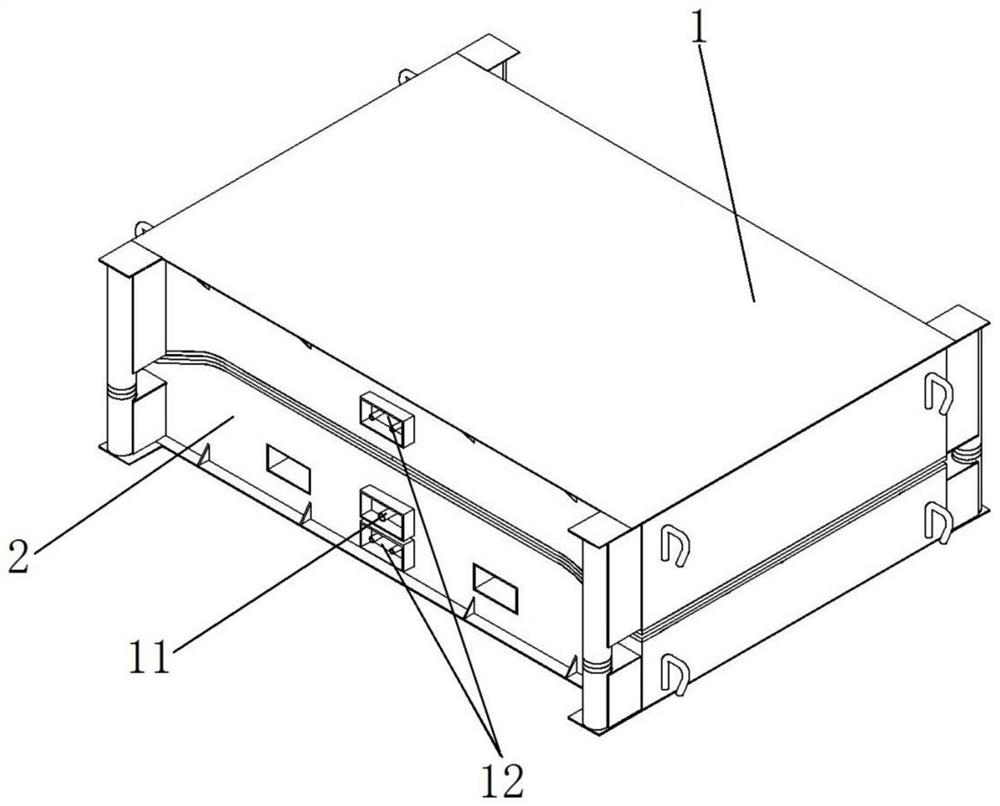
[0058] Such as figure 1 As shown, the vacuum automatic skinning mold includes an upper mold 1 and a lower mold 2. The upper mold 1 and the lower mold 2 have corresponding molding surfaces for molding products, and have a sealing structure on the periphery of the molding surface. Through the upper mold 1 and the lower mold The sealing structure of 2 and the molding surface cooperate to enclose the mold cavity. During specific production, based on the shape design of the product, it is necessary to lay a skin on the molding surface of the lower mold 2, and then fill the mold cavity with polyurethane hard foam to form the pr...

specific Embodiment 5

[0069] The specific embodiment 5 of the vacuum automatic skinning mold provided by the present invention mainly differs from the embodiment 1 in that the sealing structure in the embodiment 1 is a two-stage step structure. In this embodiment, the sealing structure is arranged on the molding surface The outer lateral street surface is a rectangular flange.

[0070] The specific embodiment of the lower mold of the vacuum automatic skinning mold in the present invention, the structure of the lower mold of the vacuum automatic skinning mold is the same as the structure, manufacturing method and use method of the lower mold in the above-mentioned vacuum automatic skinning mold embodiment 1-5, No further details will be given here.


PUM


Abstract

The invention belongs to the field of mold forming, and particularly relates to a lower mold of a vacuum automatic coating mold and the vacuum automatic coating mold, the lower mold of the vacuum automatic coating mold comprises a forming face used for forming a product and a sealing structure located on the periphery of the forming face, and the sealing structure is provided with a sealing face used for being matched with a corresponding upper mold to achieve sealing of a mold cavity. The forming surface is provided with a forming surface vacuumizing hole, so that the surface skin can be attached to the forming surface through vacuumizing, the sealing surface is provided with a sealing surface vacuumizing hole, so that the edge part of the surface skin can be sucked on the sealing surface through vacuumizing sealing, and by adopting the scheme, the edge part of the surface skin can be sucked on the sealing surface of the lower mold efficiently and conveniently at low cost; therefore, the skin can be reliably sucked on the forming surface through the forming surface vacuumizing holes.

Description

technical field [0001] The invention belongs to the field of mold forming, and in particular relates to a lower mold of a vacuum automatic skin-covering mold and a vacuum automatic skin-covering mold. Background technique [0002] Molds such as foam molds, when molding certain types of products, lay a skin on the lower mold to form the skin on the product. [0003] In order to ensure the quality of the product, it is necessary to make the skin and the molding surface of the mold fit completely and flatly. To achieve this goal, the relatively mature means of the existing technology is to install a vacuum system on the mold, and connect the vacuum system with the mold. The forming surface is connected through vacuum holes, so that the mold can be automatically covered by vacuuming. Specifically, before vacuuming, it is necessary to seal the edge of the skin with the sealing surface of the mold, so that the cavity formed by the skin and the molding surface of the mold is separ...

Claims


Application Information

Patent Timeline
Patent Type & Authority Applications(China)
IPC IPC(8): B29C44/58B29C44/34
CPCB29C44/58B29C44/34B29C44/3403
Inventor 张蕾张俊峰屈万峰
Owner 郑州豫诚模具有限公司
Why Eureka
Try Eureka