Optical storage system and optical storage scheduling method

A technology of photovoltaic storage system and photovoltaic module, which is applied in the direction of control/regulation system, photovoltaic power generation, energy storage, etc., and can solve problems such as hidden safety hazards, high cost, and high input cost

Pending Publication Date: 2022-04-26
HUAWEI DIGITAL POWER TECH CO LTD
View PDF0 Cites 1 Cited by
  • Summary
  • Abstract
  • Description
  • Claims
  • Application Information

AI Technical Summary

Problems solved by technology

[0004] However, if the optical stacking transformation is performed on the DC bus side of the computer room, not only the cost of the transformation is high, but also the optical stacking transformation on the DC bus side can only cover the DC equipment on the DC side, and the site power supply needs to have a DC access interface. The DC equipment has a DC coupling po...

Method used


Image

  • Optical storage system and optical storage scheduling method
  • Optical storage system and optical storage scheduling method
  • Optical storage system and optical storage scheduling method

Examples


Embodiment Construction

[0028] In order to make the purpose, technical solution and advantages of the application clearer, the application will be further described in detail below in conjunction with the accompanying drawings. Example embodiments may, however, be embodied in many forms and should not be construed as limited to the embodiments set forth herein; rather, these embodiments are provided so that this application will be thorough and complete, and will fully convey the concept of example embodiments to those skilled in the art. The same reference numerals denote the same or similar structures in the drawings, and thus their repeated descriptions will be omitted. The words expressing position and direction described in this application are all described by taking the accompanying drawings as an example, but changes can also be made according to needs, and all changes are included in the protection scope of this application.

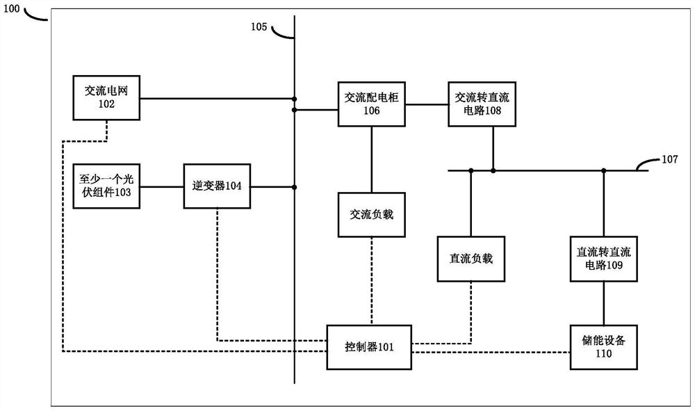
[0029] In recent years, photovoltaic-based new energy power gene...


PUM


Abstract

The system comprises a controller, an alternating current power grid, at least one photovoltaic module, an inverter, an alternating current bus, an alternating current power distribution cabinet, a direct current bus, an alternating current-to-direct current circuit, a direct current-to-direct current circuit and energy storage equipment, the alternating-current power grid is connected with the alternating-current bus; the photovoltaic module is connected with the inverter, the inverter is connected with the alternating-current bus, the alternating-current power distribution cabinet is connected with the alternating-current bus and the alternating-current-to-direct-current circuit, and the alternating-current-to-direct-current circuit is connected with the direct-current bus; the DC bus is connected with the DC-to-DC circuit; the DC-to-DC circuit is connected with the energy storage equipment; the controller is used for adjusting the energy storage device to be in a charging state or a discharging state according to the output total power of the photovoltaic module, the load total power and the load state of the alternating current power grid. By using the optical storage system provided by the invention, on the premise of reducing the optical stacking transformation cost, the difficulty of optical stacking transformation is simplified.

Description

technical field [0001] The present application relates to the technical field of photovoltaic power generation, and in particular to a photovoltaic storage system and a photovoltaic storage scheduling method. Background technique [0002] A server is a high-performance computer that provides various services. It has high reliability, availability, manageability and scalability. The server is usually located in the computer room. In order to ensure that the server can still provide normal power supply under abnormal conditions, it is necessary to perform redundant configuration on the power supply of the server. [0003] In order to redundantly configure the power supply of the server, there is a demand for light stacking transformation in the existing computer room. Among them, the superimposed photovoltaic transformation refers to: superimpose photovoltaic power supply on the basic power supply, install photovoltaic panels that meet the load power demand or exceed the load...

Claims


Application Information

Patent Timeline
IPC IPC(8): H02J3/38H02J3/32H02J3/02H02M3/155H02J7/35
CPCH02J3/381H02J3/32H02J3/02H02M3/155H02J7/35H02J2300/26Y02E10/56Y02E70/30
Inventor 武文学
Owner HUAWEI DIGITAL POWER TECH CO LTD
Why Eureka
Try Eureka