Electrically-controlled lamp picture film pasting system

A technology of stickers and diaphragms, which is applied in the field of stickers and diaphragms for electronically controlled lights, to achieve the effects of convenient battery replacement, increased support range, and overcoming the inconvenience of disassembly

Pending Publication Date: 2022-04-29
杭州三里电子科技有限公司
View PDF1 Cites 0 Cited by
  • Summary
  • Abstract
  • Description
  • Claims
  • Application Information

AI Technical Summary

Problems solved by technology

[0004] The purpose of the present invention is to overcome the disadvantages in the prior art that the connection between the control box and the sticker is easy to enter the dust, moisture, etc., which affect the stability of the sticker of the electric control lamp, and provide a connection stability between the control box and the sticker. Good and easy to replace the battery, the electronically controlled light sticker film system

Method used


Image

  • Electrically-controlled lamp picture film pasting system
  • Electrically-controlled lamp picture film pasting system
  • Electrically-controlled lamp picture film pasting system

Examples


Embodiment 1

[0029] The present invention will be further described below in conjunction with the accompanying drawings and specific embodiments.

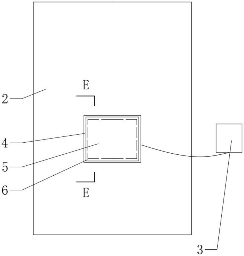
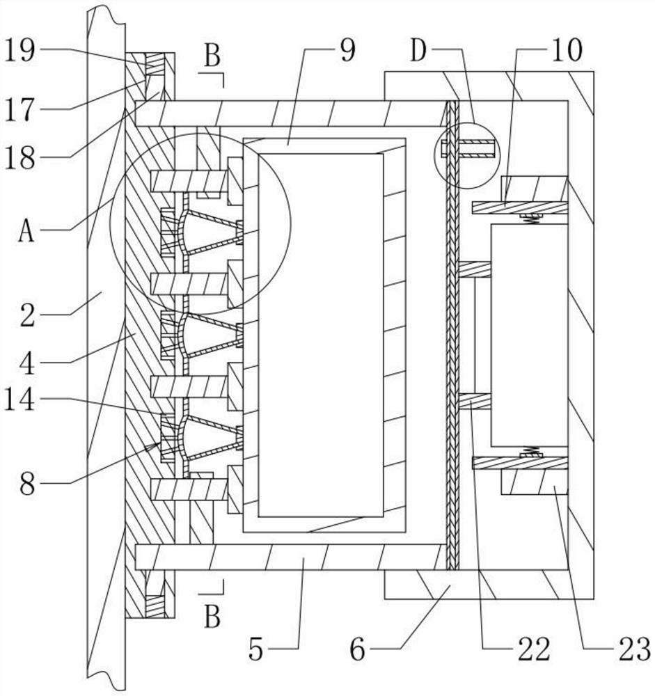
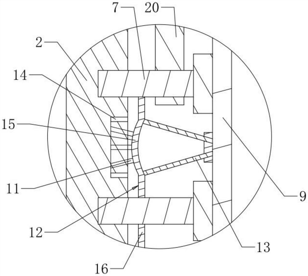
[0030] Such as figure 1 , 2 , 4, 7, and 8, an electronically controlled lamp pasting film system, including picture 1 2, picture 3 with light, connecting piece 4, protective cover 5, clamping plate 6, battery box 10, the upper part of picture 1 2 The surface is connected to the connecting piece 4, the upper surface of the connecting piece 4 is connected to the protective cover 5, the upper surface of the protective cover 5 and the connecting piece 4 forms a cavity, and a connecting column 7, a supporting device 8 and a control box 9 are arranged in the cavity, and the connecting column 7 , and the supporting devices 8 are evenly distributed on the upper surface of the connecting piece 4 . The distances between the transverse connecting columns 7 are equal, and the distances between the transverse support devices 8 are equal. The central axis...

Embodiment 2

[0042] Such as Figure 9 As shown, picture 3 (candle) with lights is located on the upper surface of picture 1 2 (Santa Claus 2) and is bonded to picture 1 2.

[0043] Bond the upper surface of picture 3 with light and picture 1 2, then connect the upper surface of connecting piece 4 and picture 1 2 with hot melt adhesive, and fix the protective cover 5 through the connecting cavity 17 at the end of connecting piece 4 The column 18 , the sealing block 19 and the connecting piece 4 are connected, and one end of the connecting column 7 is embedded with the upper surface of the connecting piece 4 . Others are the same as in Embodiment 1, and will not be repeated here.


PUM


Abstract

The invention discloses an electric control lamp picture film pasting system. The picture comprises a picture I, a picture containing a lamp, a plurality of connecting columns, a plurality of supporting devices and a control box, a connecting piece is connected to the upper surface of the picture I, a protective sleeve is connected to the upper surface of the connecting piece, a cavity is formed by the protective sleeve and the upper surface of the connecting piece, and the connecting columns, the supporting devices and the control box are all located in the cavity. One end of the supporting device is fixedly connected with the connecting piece, the other end of the supporting device is connected with the lower surface of the control box in a clamped mode, the side face of the supporting device is connected with the connecting column in a clamped mode, and the control box is electrically connected with the battery box through an arranged wire. And the battery box is clamped with the clamping plate. The invention has the beneficial effects that dust or humid gas is not easy to enter the joint of the control box and the picture I, the connection stability between the control box and the picture I is good, and the battery is convenient to replace.

Description

technical field [0001] The invention relates to the technical field of stickers, in particular to an electronically controlled lamp sticker membrane system. Background technique [0002] With the development of the economy, people's life and entertainment methods have also become rich and colorful. During important festivals, many people will paste various stickers on the window glass to increase the festive atmosphere. For example, at Christmas time, it is customary to put stickers with Santa Claus on the glass. At present, most of the stickers do not have lighting effects. In order to heighten the festive atmosphere, the stickers on the glass need an additional light projection device. However, adding a light projection device is not only cumbersome to arrange, but also takes up more space. For people with limited family space, it is very inconvenient to install a sticker with a light projection device. How to develop a sticker that is easy to install and has different l...

Claims


Application Information

Patent Timeline
IPC IPC(8): F21S9/02F21V33/00F21V23/00F21V17/10F21V31/00G09F13/00B44C5/04
CPCF21S9/02F21V33/0032F21V23/008F21V17/10F21V31/005G09F13/00B44C5/0446
Inventor 陈逢丹
Owner 杭州三里电子科技有限公司
Why Eureka
Try Eureka