Novel composite drill rod

A drill rod and a new type of technology, applied in drill rods, drilling equipment, earth-moving drilling, etc., can solve the problems of improving the strength of the end of the drill rod, breaking the drill rod, affecting the construction efficiency, etc., and achieving good connection stability and cost. Control, service life improvement effect

Inactive Publication Date: 2016-12-07
王华彬
View PDF7 Cites 0 Cited by
  • Summary
  • Abstract
  • Description
  • Claims
  • Application Information

AI Technical Summary

Problems solved by technology

However, the above-mentioned traditional integral drill rod structure makes it difficult to improve the strength of the end of the drill rod, resulting in unsatisfactory overall working strength; at the same time, in the actual working process, the above-mentioned drill rod is extremely prone to breakage Even broken, which seriously affects the construction efficiency

Method used


Image

  • Novel composite drill rod

Examples


Embodiment 1

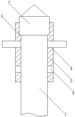
[0019] Such as figure 1 A new type of composite drill rod is shown, which includes a drill rod body 1, the end of the drill rod body 1 is provided with an alloy end portion 2, and the alloy end portion 2 adopts a tapered structure; the drill rod body 1 and the alloy end The parts 2 are connected by connecting sleeves 3, and at least one set of pin holes 4 are arranged on the connecting sleeves 3, and the drill rod body 1 and the connecting sleeves 3 are connected by pins.

[0020] As an improvement of the present invention, the novel composite drill rod is made by the following process steps:

[0021] 1) Take the seamless steel pipe according to the length requirement, and drill holes in the corresponding position of the seamless steel pipe to form pin holes, so that the seamless steel pipe forms a connecting sleeve;

[0022] 2) Insert a pin shaft into each pin hole in the connecting sleeve in step 1);

[0023] 3) Sintering the alloy end into shape, and placing the alloy end...

Embodiment 2

[0028] As an improvement of the present invention, two sets of pin holes 4 are arranged on the connecting sleeve 3 , which are uniformly distributed along the radial direction of the connecting sleeve 3 . By adopting the above-mentioned technical scheme, it can realize the connection of the drill rod body at different positions relative to the connecting sleeve through multiple sets of pin holes, so that it can be adjusted according to actual use requirements, so that the composite drill rod in this application Applicability is improved.

[0029] The remaining features and advantages of this embodiment are the same as those of Embodiment 1.

Embodiment 3

[0031] As an improvement of the present invention, at least one supporting end surface 5 is provided at the end of the connecting sleeve 3 opposite to the alloy end 2, which is arranged inside the connecting sleeve 3, and the supporting end surface 5 is perpendicular to the connection The radial direction of the sleeve 3 extends; the alloy end 2 extends to the inside of the connecting sleeve 3 and fits on the supporting end surface 5 . By adopting the above-mentioned technical solution, the setting of the supporting end surface enables the alloy end to be supported in multiple directions during forming and subsequent work, so that its working strength can be further improved.

[0032] The remaining features and advantages of this embodiment are the same as those of Embodiment 2.


PUM


Abstract

The invention discloses a novel composite drill rod. The novel composite drill rod comprises a drill rod body. An alloy end is arranged at the end of the drill rod body and is of a conical structure. The drill rod body and the alloy end are connected through a connection pipe sleeve provided with at least one set of pin holes. The drill rod body and the connection pipe sleeve are connected through pins. According to the novel composite drill rod adopting the technical scheme, a composite structure comprising the alloy end, the connection pipe sleeve and the drill rod body is adopted so that the alloy end can be prepared independent of the drill rod body, thus material improvement can be conducted independently aiming at the alloy end of the novel composite drill rod, and accordingly the cost of the whole drill rod is controlled while the alloy end keeps good work intensity.

Description

technical field [0001] The invention relates to the field of mine shaft engineering, in particular to a novel composite drill rod. Background technique [0002] The drill rod is a rock drilling tool used for drilling and excavation in mine shaft engineering. Existing drill rods often directly fix the drill rod including the tapered end on the driving tool for work. However, the above-mentioned traditional integral drill rod structure makes it difficult to improve the strength of the end of the drill rod, resulting in unsatisfactory overall working strength; at the same time, in the actual working process, the above-mentioned drill rod is extremely prone to breakage Even fracture, which seriously affects the construction efficiency. Contents of the invention [0003] The technical problem to be solved by the present invention is to provide a composite drill rod, which can improve the working strength and service life of the drill rod in the actual working process. [000...

Claims


Application Information

Patent Timeline
IPC IPC(8): E21B17/00
CPCE21B17/00
Inventor 王华彬
Owner 王华彬
Why Eureka
Try Eureka