Glass fiber reinforced plastic cooling tower

A glass fiber reinforced plastic, cooling tower technology, applied in water shower coolers, lighting and heating equipment, heat exchanger types, etc., can solve problems such as water loss, and achieve the effect of preventing water loss

Pending Publication Date: 2022-04-29
安徽鸿德玻璃钢环保设备有限公司
0 Cites 0 Cited by

AI-Extracted Technical Summary

Problems solved by technology

[0002] The FRP cooling tower uses water mist and air to exchange heat to achieve the purpose of rapid heat dissipation; in practical applications, when water mist and air heat exchange, under the ac...

Method used

Referring to Fig. 1, in the present embodiment, described shower pipe extends out of described tower body, is used to connect water supply device, and described shower pipe is provided with nozzle to form water mist conveniently, on described tower body A drain pipe 24 can also be provided, and a drain valve is installed on the drain pipe to facilitate drainage.
[0033] Of course, the air duct 15 in Embodiment 2 and Embodiment 3 can also be applied in this embodiment, which is easily thought of by those skilled in the art according to the a...

Abstract

The invention relates to a glass fiber reinforced plastic cooling tower which comprises a tower body, and a heat dissipation body, a spraying pipe and a glass fiber reinforced plastic water retaining assembly are sequentially arranged in the tower body from bottom to top. An induced draft fan is arranged above the glass fiber reinforced plastic water retaining assembly, an induced draft pipe is installed at the position, corresponding to the induced draft fan, of the tower body, an air inlet pipe is arranged on the tower body, and the air inlet pipe is located below the heat dissipation body; the air inducing pipe comprises a horizontal part, a water collecting groove is formed in the bottom of the horizontal part, a water absorbing body is arranged in the air inducing pipe and corresponds to the middle position of the water collecting groove, a water guiding pipe is arranged at the bottom end of the water collecting groove, the top end of the water guiding pipe is communicated with the water collecting groove, and the bottom end of the water guiding pipe is communicated with the interior of the tower body; an auxiliary device used for assisting the water absorption body in draining water is arranged at the position, corresponding to the water absorption body, of the top end of the horizontal part. The glass fiber reinforced plastic cooling tower provided by the invention effectively prevents water loss.

Application Domain

Trickle coolers

Technology Topic

Manufacturing engineeringMechanical engineering +3

Image

  • Glass fiber reinforced plastic cooling tower
  • Glass fiber reinforced plastic cooling tower
  • Glass fiber reinforced plastic cooling tower

Examples

  • Experimental program(4)

Example Embodiment

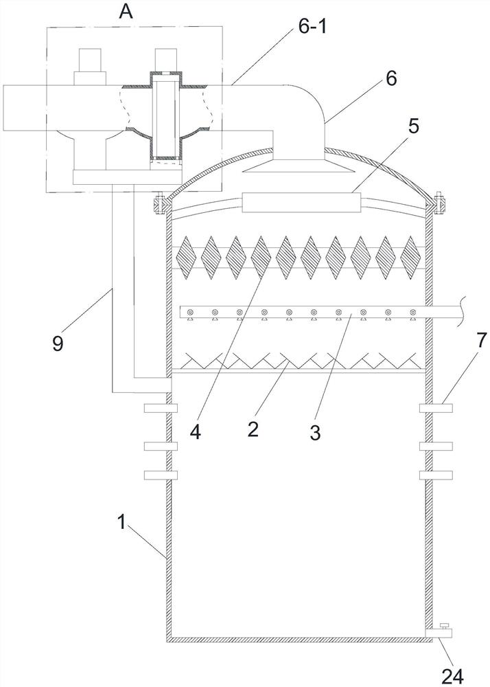
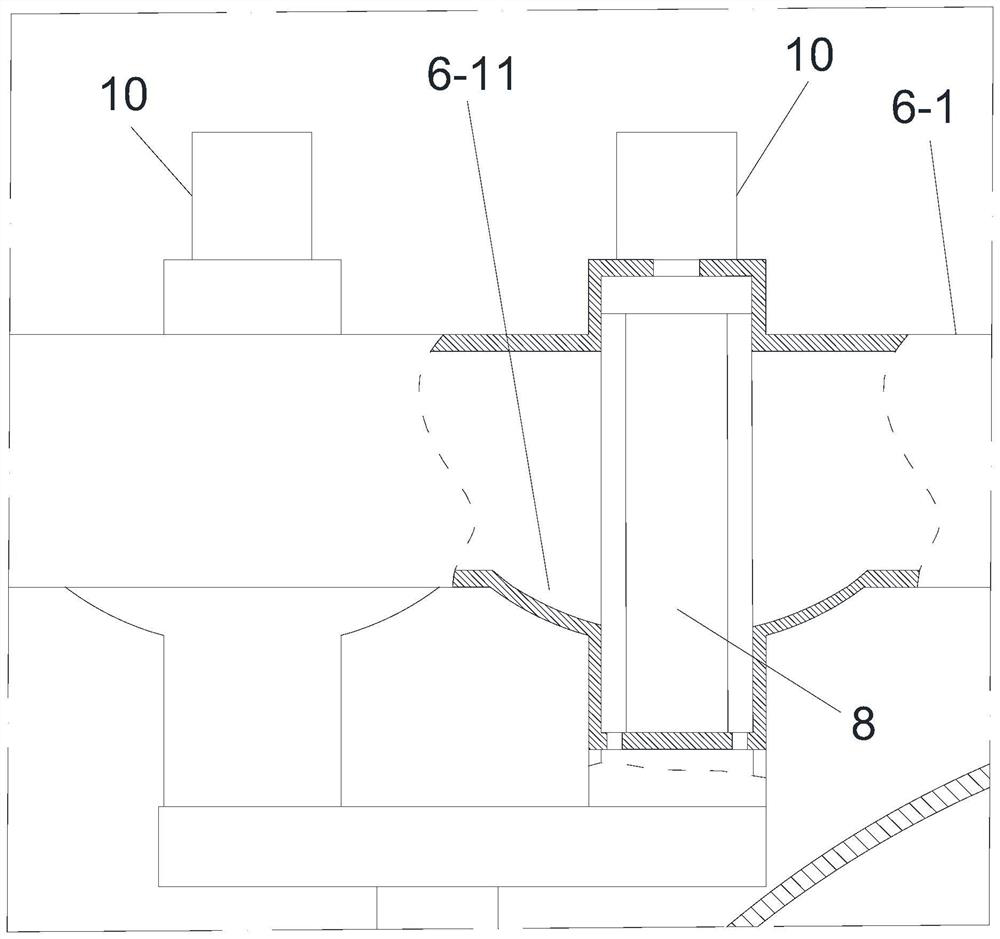
[0023] Embodiment 1, the present invention provides a kind of glass fiber reinforced plastic cooling tower, refer to figure 1 and figure 2 , including a tower body 1, the tower body is sequentially provided with a radiator 2, a spray pipe 3 and a glass fiber reinforced plastic water retaining assembly 4 from bottom to top, wherein the radiator can be an existing structure, such as cooling tower packing, cooling tower heat dissipation components, etc.; the spray pipe and the glass water blocking component can be set in the existing way; the induced draft fan 5 is arranged above the glass fiber reinforced plastic water blocking component, and the induced draft pipe is installed on the tower body corresponding to the position of the induced draft fan 6. The tower body is provided with an air inlet pipe 7, and the air inlet pipe is located below the radiator body. Generally, a filter screen and other structures are also arranged in the air inlet pipe to prevent the entry of external dust, which is in this field. It is well known to those skilled in the art; the air duct includes a horizontal portion 6-1, the bottom of the horizontal portion is provided with a water collection tank 6-11, and a water absorption body 8 is provided in the air duct corresponding to the middle position of the water collection tank, The bottom end of the water collection tank is provided with a water guide pipe 9, the top end of the water guide pipe is connected with the water collection tank, and the bottom end is connected with the interior of the tower body; The position is provided with an auxiliary device 10 for assisting the drainage of the water absorbing body. The existing structure can be used for the water absorbing body and the auxiliary device. For example, the water absorbing body is a water baffle assembly, and the auxiliary device is a vibration device; in this embodiment, the water absorbing body is preferably a sponge. Or absorbent cotton, sponge or absorbent cotton is best made into a criss-cross spliced ​​body to increase air permeability, auxiliary devices are hydraulic cylinders, air cylinders or electric telescopic rods, etc. When using hydraulic cylinders or air cylinders, it is best to use electric devices, In order to facilitate control; wherein the bottom end of the water absorbing body is fixed in the water collecting tank, and the top end of the water absorbing body is connected with the power output end of the auxiliary device. In actual production, the power output end of the auxiliary device can be connected to the plate The top of the absorbent body is connected to the plate-shaped body to increase the contact area.
[0024] When the above-mentioned FRP cooling tower is in use, when the water mist sprayed from the spray pipe exchanges heat with the air, under the action of the induced draft fan, the water vapor moves upward, and part of the water vapor is blocked by the FRP water blocking component, and the other part of the water vapor passes through the guide. After the air duct is absorbed by the water absorption body, the auxiliary device timely discharges the water absorbed by the water absorption body to the sump in a timely manner by means of extrusion or vibration, and finally transports the water absorbed by the water absorption body to the tower body through the water intake pipe. water run off.
[0025] see figure 1 , In this embodiment, the spray pipe extends out of the tower body to connect the water supply device, the spray pipe is provided with a spray head to facilitate the formation of water mist, and the tower body can also be provided with a drain pipe 24 , a drain valve is installed on the drain pipe to facilitate drainage.
[0026] In actual production, two or more sets of water absorbing bodies and auxiliary devices can be provided, so that when one hydraulic cylinder squeezes the water absorbing body, the other water absorbing body is guaranteed to be in a water-absorbing state, further improving the water recovery rate.

Example Embodiment

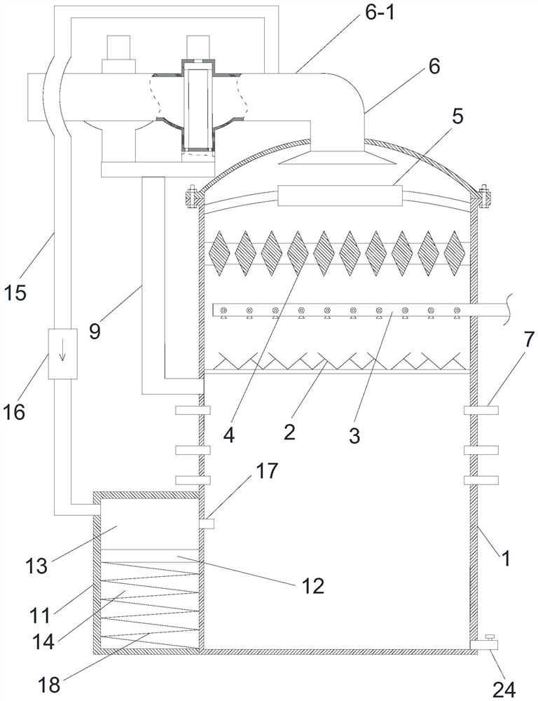
[0027] Example 2, on the basis of Example 1, the applicant also made the following design, see image 3 , the outer side of the tower body is provided with a shielding body 11, a chamber is formed between the shielding body and the tower body, a piston 12 is arranged in the chamber, and the piston divides the chamber into a first chamber chamber 13 and second chamber 14, the first chamber is located above the second chamber, an air duct 15 is arranged between the air duct and the shielding body, and the air duct is One end is connected with the air induction pipe, the connection position is located between the water collecting tank and the tower body, and the other end of the air guide pipe is connected with the shielding body, and the connection position is located at the top of the shielding body, also It is set corresponding to the first chamber; the air duct is provided with a first one-way valve 16, and the first one-way valve can make the medium (gas) in the air duct to the first chamber. A communication pipe 17 is provided on the tower body at a position corresponding to the first chamber, one end of the communication pipe is communicated with the first chamber, and the other end is communicated with the interior of the tower body; the A spring 18 is arranged in the second chamber, the top end of the spring is connected with the piston, and the bottom end of the spring is connected with the shielding body; the shielding body is located below the air inlet pipe.
[0028]In practical application, if the water absorbed by the water absorption body is not discharged in time, or the power output end of the hydraulic cylinder blocks the flow of part of the gas at the moment when the hydraulic cylinder squeezes the water absorption body, the pressure in the air duct will increase, and the pressure in the air duct will increase. If the fan is too large, the service life of the induced draft fan will be shortened or even damaged. In this embodiment, when the fan is running normally, under the action of negative pressure suction, part of the gas medium in the first chamber enters the tower body, and the piston moves upward, causing the second chamber to move upward. Negative pressure is formed and the spring is stretched. When the pressure in the air induction pipe increases, the suction force of the fan to the negative pressure in the first chamber is weakened. Under the action of the spring restoring force and negative pressure, the piston moves down, and the first chamber When the space becomes larger, a negative pressure attracts the gas in the tower, which instantly forms a buffer; at the same time, because the pressure difference between the two sides of the first one-way valve becomes larger, the gas medium in the draft pipe will enter the first chamber through the first one-way valve. Finally, it enters the tower body through the connecting pipe to form a circulation, which further forms a buffer to prevent the pressure in the draft pipe from being too large.

Example Embodiment

[0029] Example 3, on the basis of Example 1, the applicant also made the following design, see Figure 4 , the outer side of the tower body is provided with a shielding body 11, a chamber is formed between the shielding body and the tower body, a piston 12 is arranged in the chamber, and the piston divides the chamber into a first chamber chamber 13 and second chamber 14, the first chamber is located above the second chamber, an air duct 15 is arranged between the air duct and the shielding body, and the air duct is One end is connected with the air induction pipe, the connection position is located between the water collecting tank and the tower body, the other end of the air guide pipe is connected with the shielding body, and the connection position is set corresponding to the second chamber; The air duct is provided with a first one-way valve 16, and the first one-way valve can make the medium (gas) in the air duct flow in the direction of the first chamber; A communication pipe 17 is provided at a position corresponding to the first chamber, one end of the communication pipe is communicated with the first chamber, and the other end is communicated with the interior of the tower body; the tower body corresponds to the second The position of the chamber is provided with an exhaust pipe 19, one end of the exhaust pipe is communicated with the second chamber, and the other end is communicated with the interior of the tower body, and a second one-way valve is provided on the exhaust pipe 20. The second one-way valve can make the medium (gas) in the exhaust pipe flow to the inner direction of the tower body; a spring 18 is arranged in the second chamber, and the top of the spring is connected to the The piston is connected, and the bottom end of the spring is connected with the shielding body; the shielding body is located below the air inlet pipe.
[0030] In this embodiment, when the fan is running normally, under the action of negative pressure suction, part of the gas medium in the first chamber enters the tower body, and the piston moves upward, so that negative pressure is formed in the second chamber, and the spring is stretched. The pressure difference on both sides of the first one-way valve increases. When the pressure in the draft pipe increases, the pressure difference on both sides of the first one-way valve further increases, and the gas medium in the draft pipe will pass through the first one-way valve. Enter the second chamber to form a buffer; at the same time, the suction force of the fan to the negative pressure in the first chamber is weakened. Under the action of the spring restoring force and negative pressure, the piston moves down, and the space in the first chamber becomes larger to form a negative pressure suction tower. During this process, under the double action of the gas pressure in the draft pipe and the spring, part of the gas in the second chamber enters the tower body through the second one-way valve, thus forming a buffer pressure cycle; After the buffer cycle is completed, if the cause of the increase in the pressure in the air duct is eliminated, the equipment will operate normally again. If the cause of the increase in the pressure in the air duct is still not eliminated, the buffer cycle will continue. To sum up the above, the advantage of this structure is that there is a certain pressure difference on both sides of the first one-way valve when the fan is running normally, so that when the pressure in the air duct increases slightly, it can be formed on both sides of the first one-way valve. If the pressure difference is large, the first one-way valve can be quickly turned on and the response is more rapid; after the cause of the increase in the pressure in the air duct is eliminated, the equipment can automatically operate normally.

PUM

no PUM

Description & Claims & Application Information

We can also present the details of the Description, Claims and Application information to help users get a comprehensive understanding of the technical details of the patent, such as background art, summary of invention, brief description of drawings, description of embodiments, and other original content. On the other hand, users can also determine the specific scope of protection of the technology through the list of claims; as well as understand the changes in the life cycle of the technology with the presentation of the patent timeline. Login to view more.

Similar technology patents

Cleaning and skincare makeup remover

InactiveCN106137826Aprevent water lossPromotes breakdown of fibroblasts
Owner:张进

Classification and recommendation of technical efficacy words

  • prevent water loss

Cleaning and skincare makeup remover

InactiveCN106137826Aprevent water lossPromotes breakdown of fibroblasts
Owner:张进
Why Eureka
Try Eureka