Novel metal material plate bending detection device

A detection device and new material technology, applied in measuring devices, analyzing materials, testing the strength of materials by applying a stable bending force, etc. The effect of applying force and improving work efficiency

Inactive Publication Date: 2022-04-29
江苏国帆薄板科技有限公司
View PDF0 Cites 1 Cited by
  • Summary
  • Abstract
  • Description
  • Claims
  • Application Information

AI Technical Summary

Problems solved by technology

[0005] Aiming at the deficiencies of the prior art, the present invention provides a new metal material plate bending detection device, which has the advantages of clamping plates of different th

Method used


Image

  • Novel metal material plate bending detection device
  • Novel metal material plate bending detection device
  • Novel metal material plate bending detection device

Examples


Example Embodiment

[0020] Example 1:

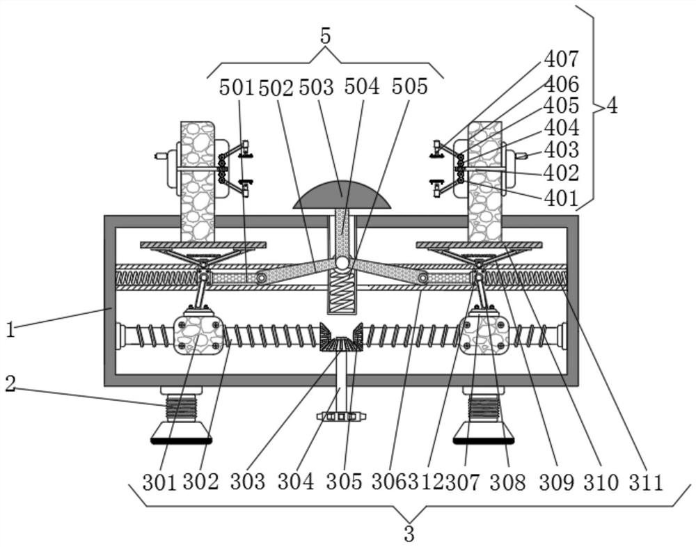
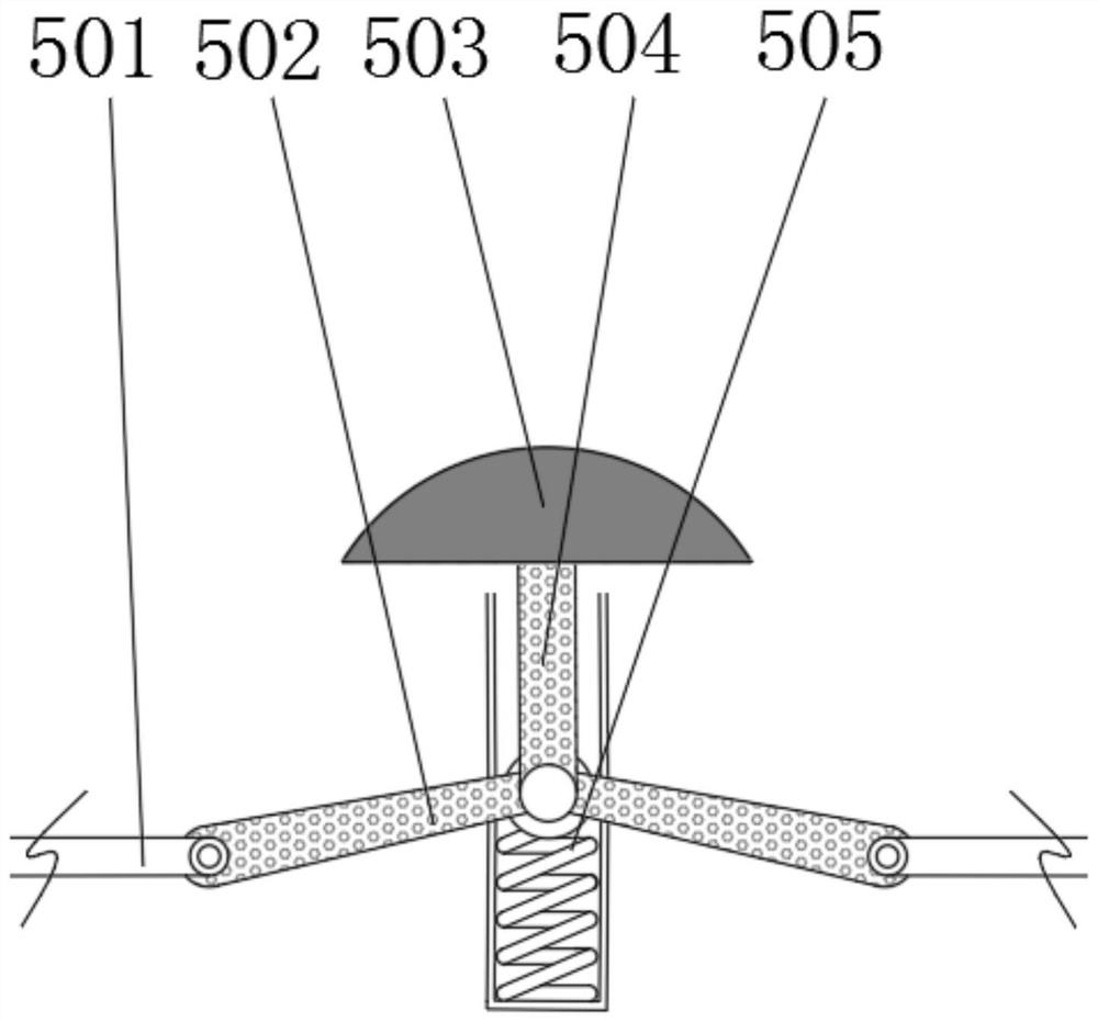
[0021] see figure 1 and 3 , a new metal material sheet bending detection device, comprising a device main body 1, a supporting leg 2 is fixedly connected to the bottom of the device main body 1, a transmission device 3 is fixedly connected to the inside of the device main body 1, and the left and right sides of the transmission device 3 are provided with The middle of the clamping device 4 and the transmission device 3 is provided with a bending device 5 .

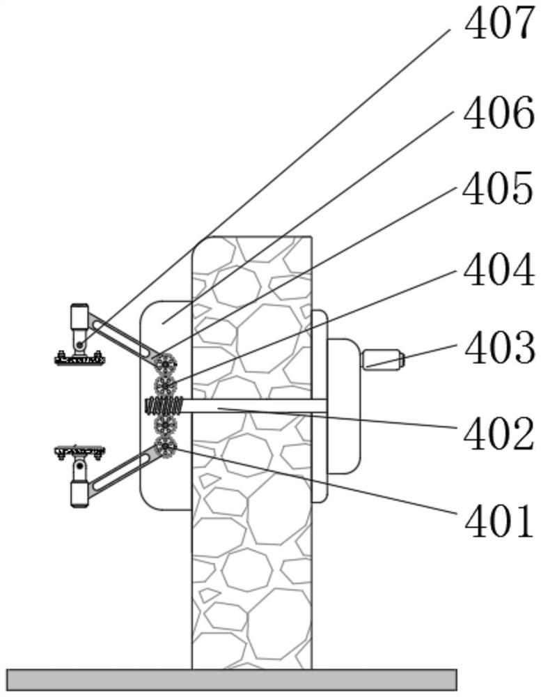
[0022] Further, the clamping device 4 includes a fixing base 406, a micro-threaded rod 402 is rotatably connected above the fixing base 406, a handle 403 is fixedly connected to the side of the micro-threaded rod 402 away from the bending device 5, and the micro-threaded rod 402 is close to the bending One side of the device 5 is meshed with a second gear 404, the side of the second gear 404 away from the micro-threaded rod 402 is meshed with a first gear 401, and a side of the first gear 401 close to...

Example Embodiment

[0024] Embodiment 2:

[0025] see Figure 1-3 , a new metal material sheet bending detection device, comprising a device main body 1, a supporting leg 2 is fixedly connected to the bottom of the device main body 1, a transmission device 3 is fixedly connected to the inside of the device main body 1, and the left and right sides of the transmission device 3 are provided with The middle of the clamping device 4 and the transmission device 3 is provided with a bending device 5 .

[0026] Further, the transmission device 3 includes an output shaft 304, the top of the output shaft 304 is fixedly connected with a first bevel gear 303, and the left and right sides of the first bevel gear 303 are meshed with a second bevel gear 305. A threaded rod 302 is fixedly connected to the side of the gear 305 away from the output shaft 304 , a threaded block 301 is threadedly connected to the side of the threaded rod 302 away from the output shaft 304 , and a mounting plate 307 is fixedly conn...


PUM


Abstract

The invention relates to the technical field of plate detection, and discloses a novel metal material plate bending detection device which comprises a device body, supporting legs are fixedly connected to the bottom of the device body, a transmission device is fixedly connected to the interior of the device body, and clamping devices are arranged on the left side and the right side of the transmission device. A bending device is arranged in the middle of the transmission device. According to the novel metal material plate bending detection device, an external motor drives an output shaft, the output shaft drives a second bevel gear through a first bevel gear, the second bevel gear drives a threaded rod to rotate, the threaded rod drives a threaded block to move, and the threaded block drives a sliding block to move in a sliding groove through a connecting rod; the sliding block drives the mounting base to move through the pressed rod, the mounting base drives the clamping device to move, meanwhile, the sliding block pushes the bent rod to move through the transverse rod, the bent rod jacks the vertical rod upwards, the vertical rod pushes the bending head to move upwards so as to extrude the plate, and the detection work of the plate is achieved.

Description

technical field [0001] The invention relates to the technical field of plate detection, in particular to a bending detection device for new metal material plates. Background technique [0002] New materials refer to newly developed or developing structural materials with excellent performance and functional materials with special properties. Structural materials mainly use their mechanical properties such as strength, toughness, hardness, and elasticity, such as new metal materials. When testing plate-shaped high-performance composite materials in new metal materials, the bending strength is often tested. [0003] At present, when the metal new material sheet bending detection device on the market conducts continuous detection tests on plate-shaped high-performance composite materials, it cannot continuously and stably clamp materials of different thicknesses, and the traditional metal new material sheet bending detection device cannot continue. Stable force is provided, an...

Claims


Application Information

Patent Timeline
IPC IPC(8): G01N3/20G01N3/02
CPCG01N3/20G01N3/02
Inventor 郝兴亮
Owner 江苏国帆薄板科技有限公司
Why Eureka
Try Eureka