
Integrated ejector, fuel cell hydrogen supply system and control method of fuel cell hydrogen supply system

A technology of ejector and controller, which is applied in the field of fuel cells, can solve the problems of complicated ejector structure design, inability to meet the rapid response of sudden rise and fall, and difficult coverage of ordinary ejectors, etc.

Pending Publication Date: 2022-04-29
宁波赛轲动力科技有限公司
View PDF0 Cites 0 Cited by
  • Summary
  • Abstract
  • Description
  • Claims
  • Application Information

AI Technical Summary

Problems solved by technology

However, it is difficult for ordinary ejectors to cover all the working conditions required by the stack load
Therefore, at present, the ejector and small compressor are connected in parallel to cover all working conditions, but the small compressor is introduced as additional equipment, which brings additional power consumption, noise, volume, and complicated pipeline design. The original intention of the ejector to reduce energy consumption has not been achieved
Later, two nozzles were connected in parallel, and different nozzle inlets were selected according to the conditions, but this design brought about a delayed response in control, and the load accuracy was low, and the structure design of the ejector was complicated.
At this stage, there is still a method of adding a needle regulator to the nozzle of the ejector to achieve all working conditions by adjusting the nozzle section, but the needle regulator needs an additional motor to drive, with additional power consumption and noise. and other problems, and this method cannot meet the rapid response of sudden rise and fall. In addition, due to the small nozzle, the eccentricity error of the needle regulator setting is high, and there is a problem of unstable use.

Method used


Image

  • Integrated ejector, fuel cell hydrogen supply system and control method of fuel cell hydrogen supply system
  • Integrated ejector, fuel cell hydrogen supply system and control method of fuel cell hydrogen supply system
  • Integrated ejector, fuel cell hydrogen supply system and control method of fuel cell hydrogen supply system

Examples


Embodiment

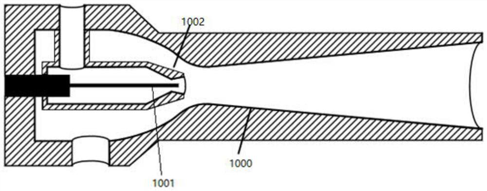
[0046] Discovered by the inventor, the ejector 1000 of prior art, please refer to figure 1 , the existing nozzle 1002 is pierced with a variable adjusting needle 1001, the section of the nozzle is adjusted through the adjusting needle 1001 in the existing nozzle 1002, so that the hydrogen can reach the critical speed in the nozzle under various working conditions and reach the induction But the adjustment needle 1001 needs an additional motor to drive, which introduces problems such as extra power consumption and noise, and the response is delayed, so it cannot quickly meet the needs of load changes. In addition, due to the small nozzle, the eccentricity of the adjustment needle 1001 setting The error is high and the use is unstable.

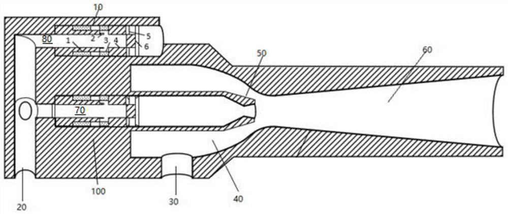
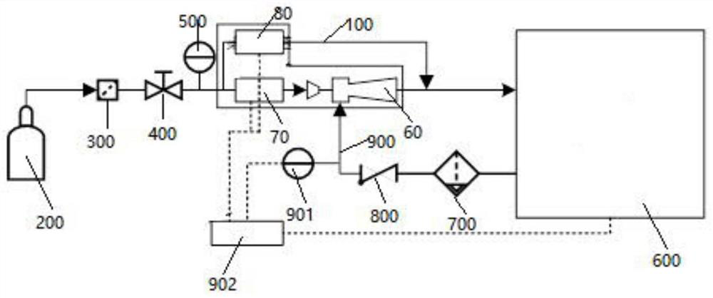
[0047] In view of this, the embodiment of this application provides an integrated ejector, please refer to figure 2 , the integrated ejector 100 is used with the stack 600 of the fuel cell ( image 3 shown in ), the integrated ejector 100 inc...


PUM


Abstract

The embodiment of the invention provides an integrated ejector, a fuel cell hydrogen supply system and a control method thereof, and belongs to the technical field of fuel cells. The integrated ejector comprises a main gas passage, a first flow passage, a second flow passage, a nozzle, a circulating gas passage, an ejection chamber and a mixing chamber, the main gas passage is used for introducing high-pressure hydrogen of a hydrogen supply system of the fuel cell, the main gas passage is communicated with the first flow passage and the second flow passage, a first opening and closing unit is arranged on the first flow passage, and a second opening and closing unit is arranged on the second flow passage; the dynamic flow of the first flow channel and the second flow channel can be adjusted by controlling the circulating opening and closing duration of the first opening and closing unit and the second opening and closing unit. Two runners are designed in the ejector and opening and closing of the runners are controlled, so that the ejection amount and the load supplement amount are accurately provided, the wide-area ejection range and sudden-rising and sudden-falling load changes are quickly responded, the size is simple, additional energy consumption is avoided, complex adjusting equipment is omitted, and the cost is reduced. And the hydrogen supply requirements of the fuel cell under various complex working conditions are effectively improved.

Description

technical field [0001] The present application relates to the technical field of fuel cells, in particular, to an integrated injector, a fuel cell hydrogen supply system and a control method thereof. Background technique [0002] In the fuel cell design, introducing a hydrogen supply circulation system in the anode circuit can improve the efficiency of the stack. As a booster device with no energy consumption and simple pipeline, the ejector has more advantages than the compressor in the hydrogen supply cycle system. However, it is difficult for ordinary ejectors to cover all the working conditions required by the stack load. Therefore, at present, the ejector and small compressor are connected in parallel to cover all working conditions, but the small compressor is introduced as additional equipment, which brings additional power consumption, noise, volume, and complicated pipeline design. The original intention of the ejector to reduce energy consumption has not been ach...

Claims


Application Information

Patent Timeline
IPC IPC(8): H01M8/04H01M8/04089H01M8/04298
CPCH01M8/04H01M8/04089H01M8/04298Y02E60/50
Inventor 鲍不平支明照沈伟达
Owner 宁波赛轲动力科技有限公司
Learn More