Portable fuel cell power supply

Inactive Publication Date: 2005-09-15
RICHARDS WILLIAM R +2
View PDF1 Cites 30 Cited by
  • Summary
  • Abstract
  • Description
  • Claims
  • Application Information

AI Technical Summary

Benefits of technology

[0011] It is a further object of the invention to provide hydrogen as the source of fuel for the fuel cell to be contained in a cylinder storage system an

Problems solved by technology

Although volumetrically efficient, a metal hydride storage cylinder as a hydrogen supply is disadvantageous because of its weight.
Reformer-based technologies for hydrogen gas generation, using liquid hydrocarbon fuels are not known to be readily available.
The consideration of using of high pressure hydrogen gas storage systems has previously been limited to the use of rechargeable “lecture bottle” size pressure vessels, typically providing less than one (1) pint cap

Method used


Image

  • Portable fuel cell power supply
  • Portable fuel cell power supply
  • Portable fuel cell power supply

Examples


case 10

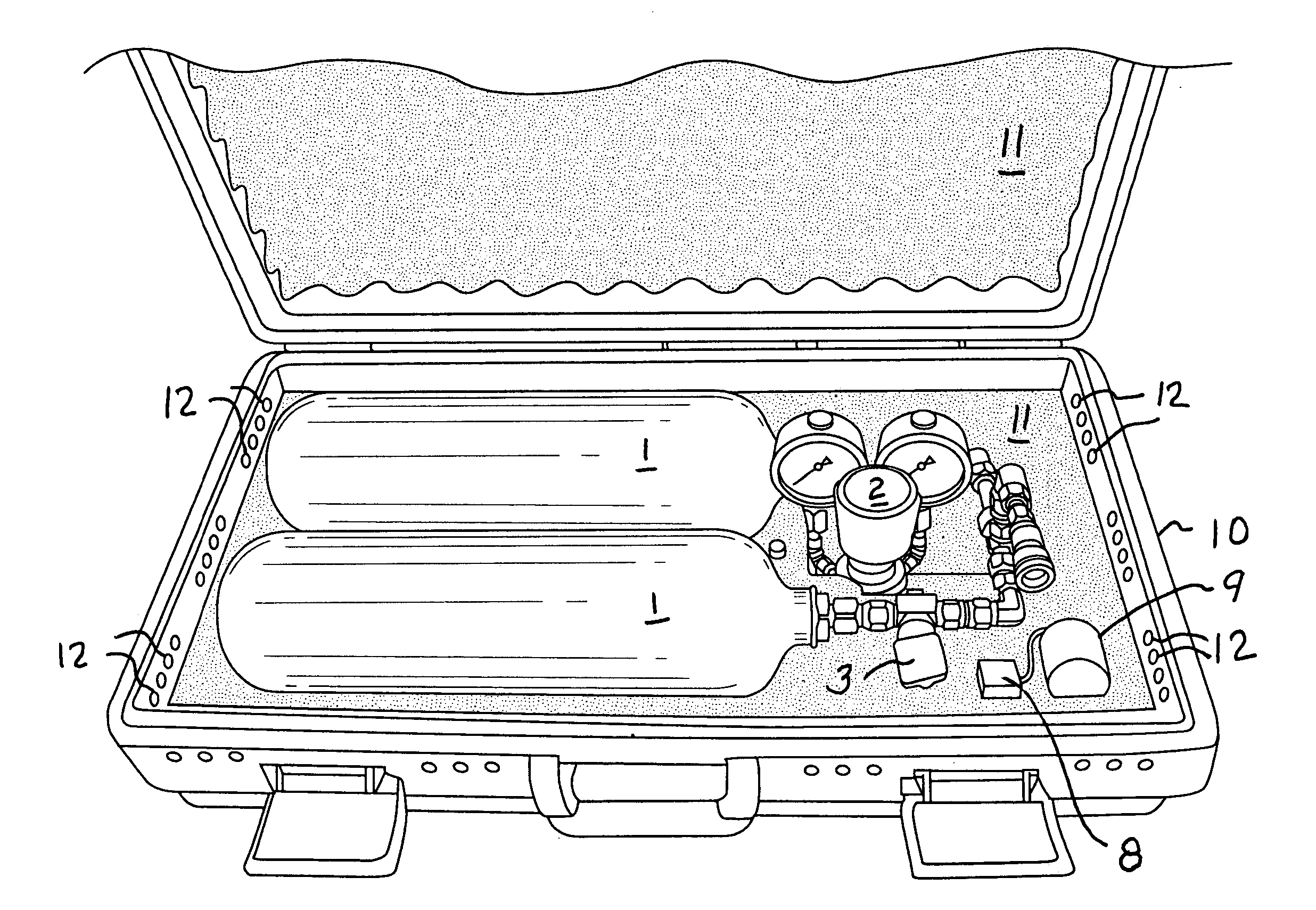
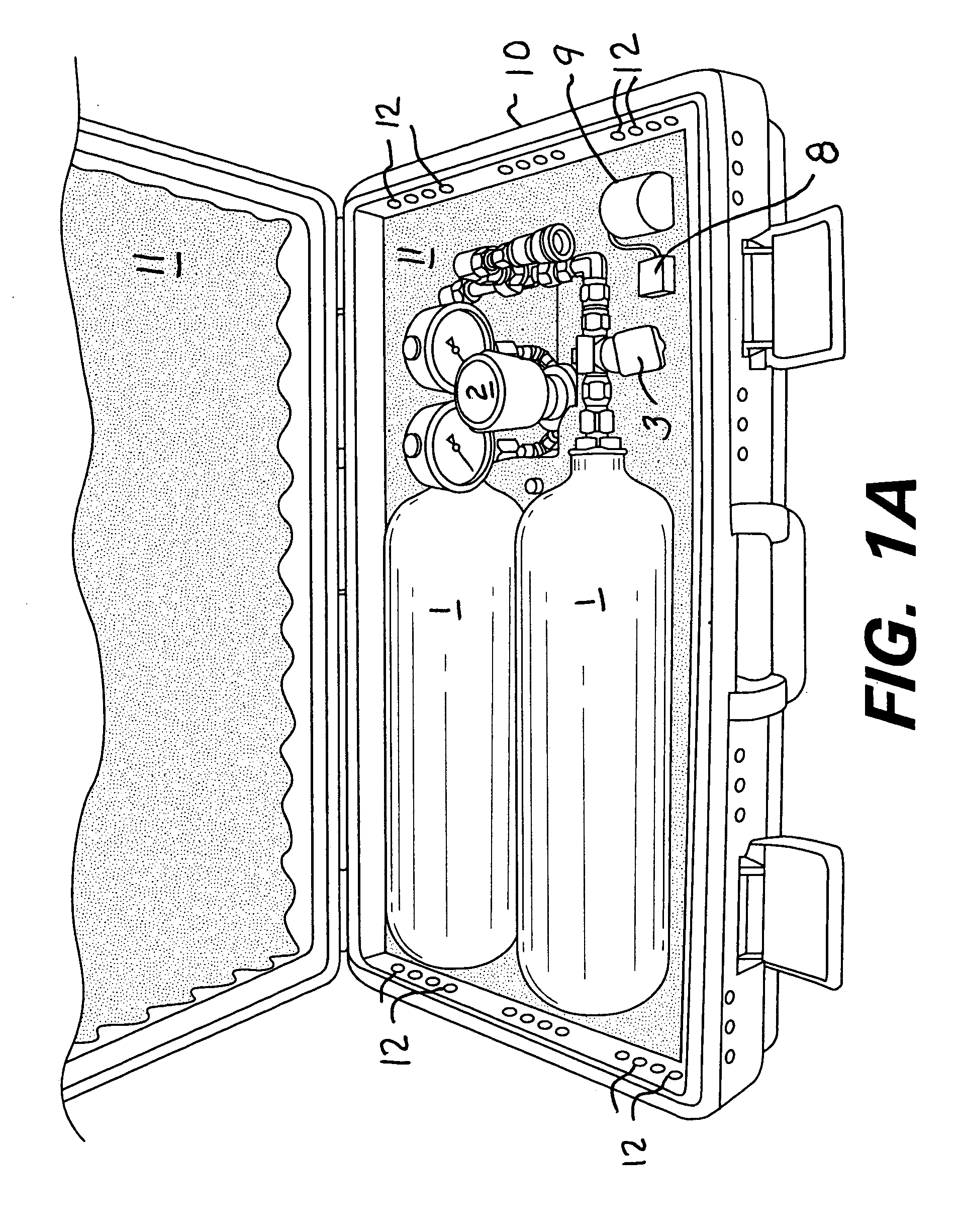
[0022] Case 10 preferably includes additional features to assure that undetectable leakage rate effects (i.e., approximately 0.125 cc / hour) do not raise the concentration of the hydrogen gas in the case above 0.8% by volume to air, which provides an ample margin of safety. This capability is provided by a multiplicity of ventilation holes 12 arrayed about the free-space volume between the upper and lower halves of case 10. These holes facilitate the unimpeded (free) circulation of air within the case envelope, and permit air exchange to occur at rates at or below 0.3 FPM, or approximately 0.3 SCFH. This is the equivalent of making a complete change in the volume of air contained within the case approximately once every four hours. Increasing the number of holes by a factor of two or more would allow a proportional increase in the overall design margin of safety.

[0023] Case 10 preferably provides a fully-integrated hydrogen supply system with all necessary connection interfaces neces...

case 20

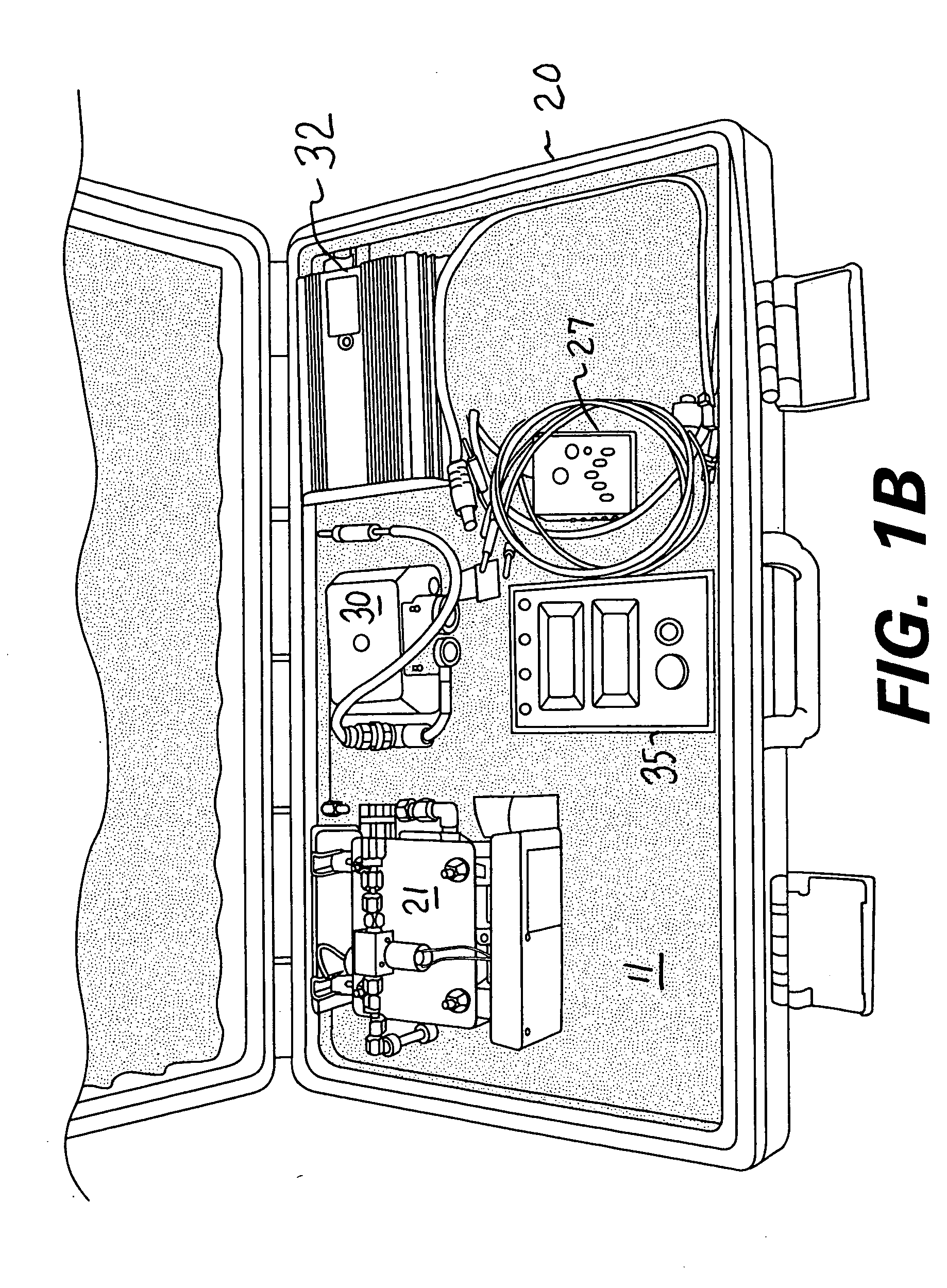
[0031] Case 20 provides features to assure for the safe operation of the fuel cell stack under all operational conditions, by integration of failsafe hydrogen isolation valve 23 (FIG. 4) at the hydrogen inlet 22 (FIG. 2) of the fuel cell stack. A hydrogen sensor 27 in case 20 used during operation of the fuel cell (FIG. 4) senses hydrogen concentration levels, and a temperature sensor 41 detects temperature of the fuel cell stack (FIG. 4). If the level of detected hydrogen exceeds 1% by volume, or if the sensing of an over-temperature condition on the stack itself occurs, hydrogen supply to the stack will be completely isolated by isolation valve 23 to prevent any significant release of hydrogen directly into the environment. Additional safety features include overload sensing for either 12 VDC, 24 VDC or 115 VAC power generation in the inverter.

[0032] The power supply of the invention is capable of storing hydrogen gas at pressures of 3000 psig, with associated design pressure rati...


PUM


Abstract

A portable proton exchange membrane fuel cell power supply system has a high pressure hydrogen gas supply that is provided from hydrogen storage cylinders that are enclosed in a case that has through holes for ventilation to prevent hydrogen gas concentrations from reaching explosive levels. Enclosed in a second case are a fuel cell stack, control unit, variable speed air compressor and power inverter. The cases incorporate lightweight, high-strength non-metallic materials and foam insulation to render the contents shock resistant. In operation a hydrogen gas connection line is made to extend between the hydrogen cylinders and the fuel cell that is connected through quick disconnect valves. The compressor is also connected to the fuel cell through a quick disconnect valve. Start up of the fuel cell is accomplished with a battery supplying power to the compressor while hydrogen gas is supplied at the same time.

Description

FIELD OF THE INVENTION [0001] The invention relates to a portable power supply that has a fuel cell for generating power from a source of hydrogen gas. BACKGROUND OF THE INVENTION [0002] A need exists for a portable power generation system or power supply that is capable of providing continuous or intermittent power over a period of time. Such a power supply must have its own source of hydrogen gas, in the case of a proton exchange membrane fuel cell (PEMFC). [0003] Prior art solutions have typically relied on the use of metal hydride containment systems for providing a source of relatively low pressure (i.e., typically 200 to 300 psig) storage of hydrogen gas. A metal hydride storage cylinder provides the capability to achieve up to a 2.5 to 3× improvement in the amount of hydrogen gas that may be contained within a defined containment volume versus that of an equivalent high pressure (2600 to 3000 psig) gas storage system. [0004] Although volumetrically efficient, a metal hydride ...

Claims


Application Information

Patent Timeline
IPC IPC(8): H01M8/04H01M8/10
CPCH01M8/04089H01M8/04201H01M8/04208H01M8/0432H01M8/04365Y02B90/18H01M8/04664H01M8/04686H01M2008/1095H01M2250/30Y02E60/50H01M8/0444Y02B90/10
Inventor RICHARDS, WILLIAM R.VOLKER, ALAN L.BRAR, JASPAL
Owner RICHARDS WILLIAM R
Why Eureka
Try Eureka