Mixed filling system applied to hydrogen filling station of liquid hydrogen

A filling system and hydrogen refueling station technology, applied in the direction of hydrogen technology, container discharge methods, equipment loaded into pressure vessels, etc. Issues such as fluence requirements to achieve the effect of increasing hydrogen storage capacity

Pending Publication Date: 2018-09-21
ZHANGJIAGANG RES INST OF HYDROGEN ENERGY CO LTD
View PDF0 Cites 30 Cited by
  • Summary
  • Abstract
  • Description
  • Claims
  • Application Information

AI Technical Summary

Problems solved by technology

The disadvantages of the current hydrogen refueling stations using high-pressure technology for hydrogen storage are: 1. The hydrogen storage capacity is low. The daily hydrogen refueling capacity is 200kg / day, which can only basically meet the refueling requirements of vehicles during small-scale demonstration operations, and cannot meet the requirements of With the development of the hydrogen fuel cell vehicle industry and the increasing demand for filling volume
2. It can only be filled with high-pressure hydrogen, and its filling form is single. It can only serve high-pressure hydrogen fuel cell vehicles, and it cannot fill liquid hydrogen fuel cell vehicles.

Method used


Image

  • Mixed filling system applied to hydrogen filling station of liquid hydrogen

Examples


Embodiment Construction

[0014] The present invention will be further described in detail below in conjunction with the accompanying drawings and preferred embodiments.

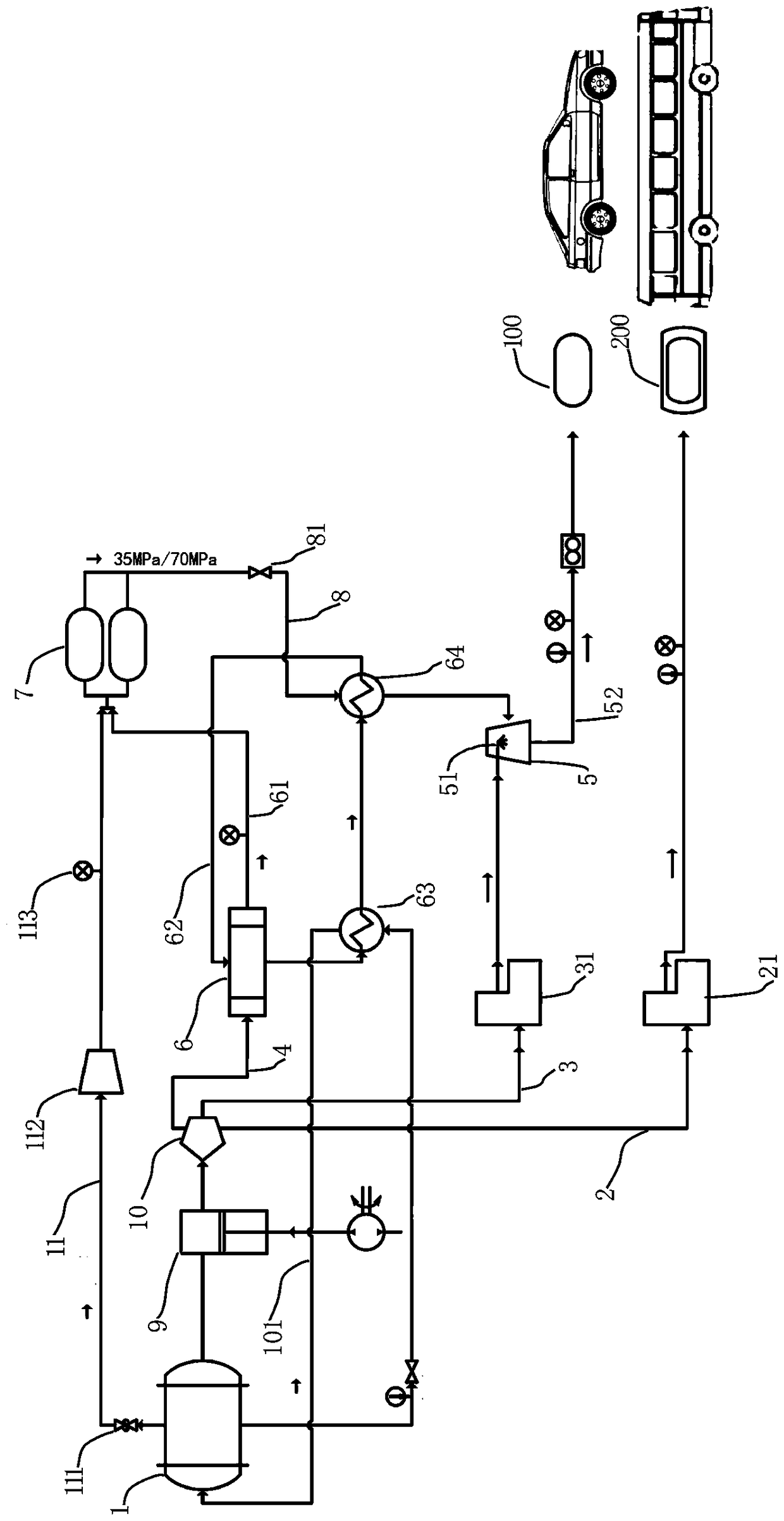
[0015] Such as figure 1 As shown, the mixed filling system applied to the liquid hydrogen refueling station includes a liquid hydrogen filling unit and a high-pressure hydrogen filling unit for connecting with the liquid hydrogen storage tank 1 for the station.

[0016] The structure of the liquid hydrogen filling unit includes: the first liquid hydrogen delivery pipe 2, the first liquid hydrogen delivery pipe 2 can communicate with the station liquid hydrogen storage tank 1 through the liquid hydrogen pump 9, the first liquid hydrogen delivery pipe The output end of 2 is used to connect the liquid hydrogen filling gun. In this embodiment, the first liquid hydrogen delivery pipe 2 is provided with a first metering pump 21 .

[0017] The structure of the high-pressure hydrogen filling unit includes: the second liquid hydrogen delive...


PUM


Abstract

The invention discloses a mixed filling system applied to a hydrogen filling station of liquid hydrogen. The mixed filling system comprises a liquid hydrogen filling unit and a high-pressure hydrogengas filling unit which are connected with a liquid hydrogen storage pot for the station, wherein a first liquid hydrogen conveying pipe in the liquid hydrogen filling unit can be communicated with theliquid hydrogen storage pot for the station through a liquid hydrogen pump; an output end of the first liquid hydrogen conveying pipe is used for connecting a liquid hydrogen filling gun; the high-pressure hydrogen gas filling unit comprises a second liquid hydrogen conveying pipe and a third liquid hydrogen conveying pipe which can be communicated with the liquid hydrogen storage pot for the station through the liquid hydrogen pump; the second liquid hydrogen conveying pipe is communicated with a spraying nozzle in a gas-liquid mixer; the third liquid hydrogen conveying pipe is communicatedwith a vaporizer; a gas output pipe on the vaporizer is communicated with a high-pressure hydrogen gas hydrogen storage bottle; a storage bottle output pipeline of an output end of the high-pressure hydrogen gas hydrogen storage bottle is communicated to the gas-liquid mixer; a hydrogen gas output pipe of the output end of the gas-liquid mixer is used for being connected with a high-pressure hydrogen gas filling gun. The mixed filling system has the advantages that a hydrogen filling form is effectively increased and the liquid hydrogen capability is greatly improved.

Description

technical field [0001] The invention relates to the technical field of liquid hydrogen refueling stations, in particular to a filling system for liquid hydrogen refueling stations. Background technique [0002] Hydrogen refueling stations are mainly used to refuel hydrogen fuel cell vehicles. At present, the hydrogen refueling stations built in my country mainly use high-pressure technology to store hydrogen gas sources. Please refer to the hydrogen compression gas storage system of mechanical hydrogen refueling stations disclosed in the application number 2016105472243. The disadvantages of the current hydrogen refueling stations using high-pressure technology for hydrogen storage are: 1. The hydrogen storage capacity is low. The daily hydrogen refueling capacity is 200kg / day, which can only basically meet the refueling requirements of vehicles during small-scale demonstration operations, and cannot meet the requirements of With the development of the hydrogen fuel cell ve...

Claims


Application Information

Patent Timeline
Patent Type & Authority Applications(China)
IPC IPC(8): F17C5/04F17C5/06F17C7/04F17C13/00
CPCF17C5/04F17C5/06F17C7/04F17C13/00F17C2221/012F17C2223/0169F17C2225/0123F17C2225/0169F17C2227/0142F17C2227/039F17C2265/065Y02E60/32Y02P90/45
Inventor 倪中华严岩魏蔚王秋霞何春辉奚天洋刘志伟
Owner ZHANGJIAGANG RES INST OF HYDROGEN ENERGY CO LTD
Why Eureka
Try Eureka