Hydrogen supply pressure regulator

a technology of pressure regulator and hydrogen gas, which is applied in the direction of fluid pressure control, process and machine control, instruments, etc., can solve the problems of difficult design flow control and difficulty in controlling hydrogen gas flow, and achieve the effects of preventing hydrogen leakage, low friction, and easy lengthening and shortening

Inactive Publication Date: 2009-10-01
GM GLOBAL TECH OPERATIONS LLC
View PDF19 Cites 31 Cited by
  • Summary
  • Abstract
  • Description
  • Claims
  • Application Information

AI Technical Summary

Benefits of technology

[0012]In many embodiments of the invention, the regulator body will also be shaped to accommodate a coil spring (or other expanding device) to exert a predetermined force on the stem side of the piston head. The portion of the regulator body containing the spring is typically vented to the atmosphere so that this chamber of the body does not see hydrogen flow and is maintained at atmospheric pressure. But high pressure hydrogen acts on the piston stem and enters the axial flow passage through the stem and piston head. And lower pressure hydrogen acts on the piston head against the spring force. It is the response of the piston to spring force acting on one side of the piston head and hydrogen gas pressure acting on the other side of the piston head that prompts movement of the piston head and stem toward and away form the sealing seat of the hydrogen gas inlet. The regulator structure so far described accounts for the regulating function of the device. But means must be provided for preventing leakage of hydrogen within and from the regulator and for permitting low friction movement of the piston along the axis of the regulator.
[0013]In accordance with some embodiments of the invention, a first tubular bellows of corrugated shape is used to confine higher pressure hydrogen gas around the piston stem and the opening into the stem passage. The first bellows may also prevent hydrogen from enterin

Problems solved by technology

This substantial range in pressures and temperatures makes it difficult to control hydrogen gas flow.
It has been difficult to design flow control pressure regulators that are effective and e

Method used


Image

  • Hydrogen supply pressure regulator
  • Hydrogen supply pressure regulator
  • Hydrogen supply pressure regulator

Examples


Embodiment Construction

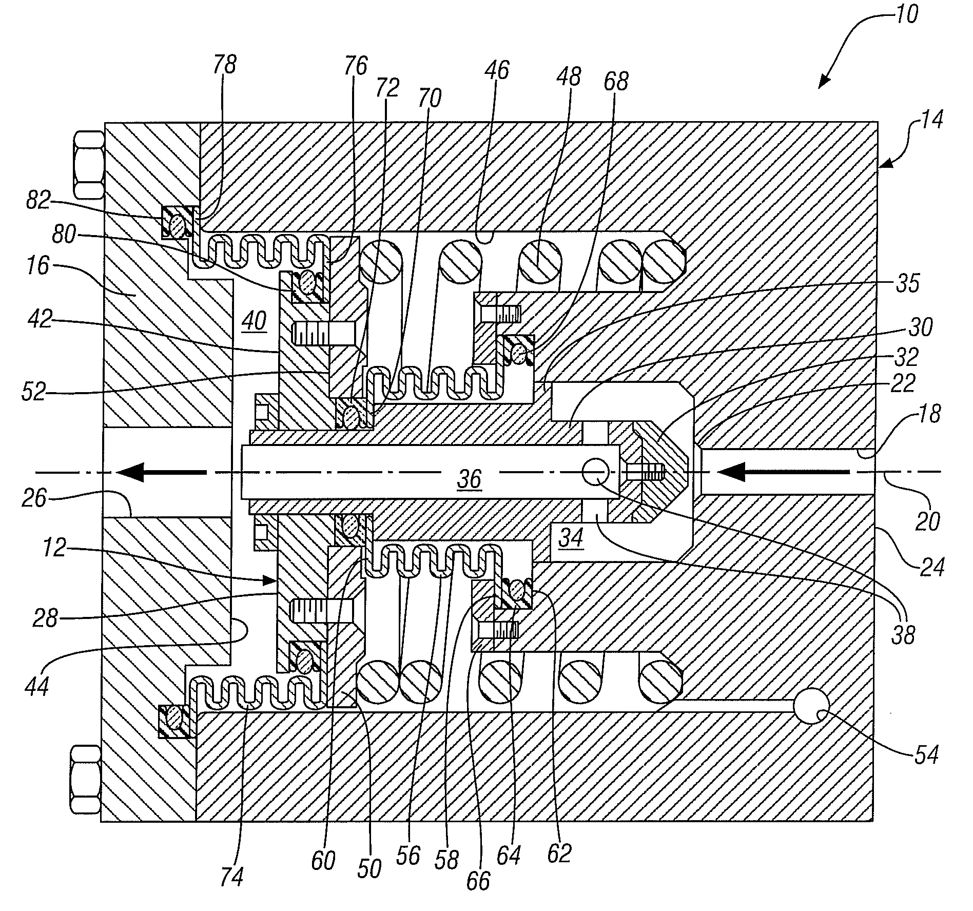
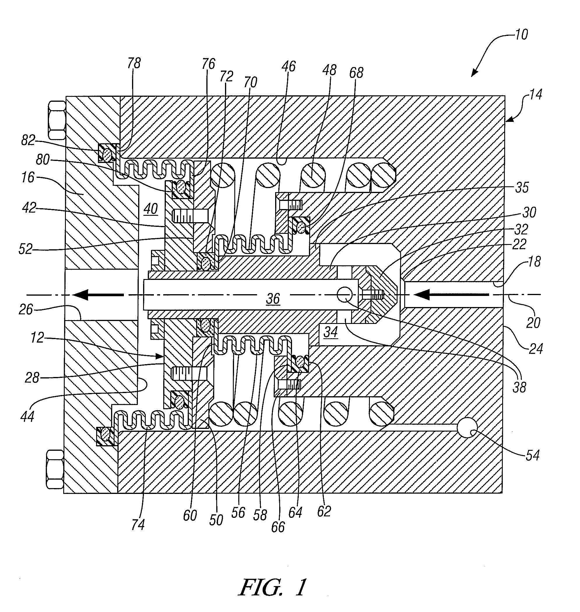
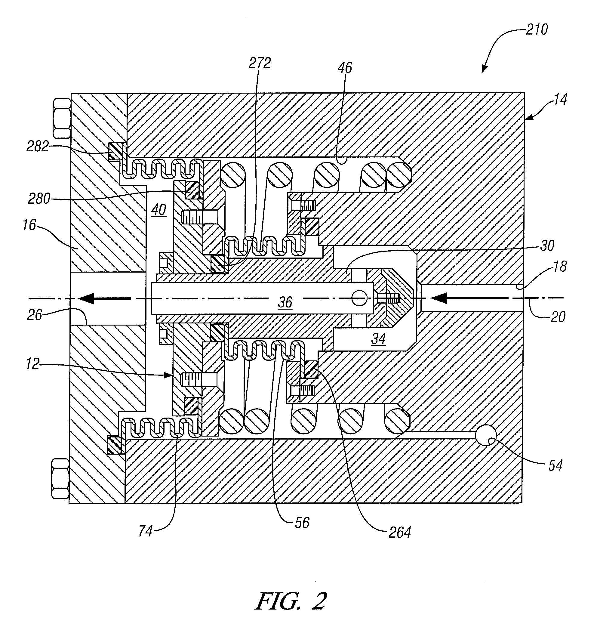
[0024]In accordance with an embodiment of the invention, a pressure regulator described herein provides a regulator body that contains an interior piston assembly to control fluid flow through the regulator, especially hydrogen gas flow. The outlet pressure of the pressure regulator may remain substantially unaffected by variations in the relatively high inlet pressure by relying upon direct outlet pressure feedback to control the fluid pressure. A high pressure chamber is formed on one side of a piston head and a low pressure chamber on the other side. A combination of bellows and seals are used to define the chambers, thus minimizing leakage of hydrogen and facilitating low friction movement of a piston module. The pressure regulator uses a compressive force balance across the piston assembly to maintain the regulator outlet pressure at a predetermined pressure or set point. Examples of some preferred high-pressure regulators are described in the following specification.

[0025]Refe...


PUM


Abstract

Hydrogen gas flow from high pressure storage to a lower pressure hydrogen-using device is managed using one or more axial flow pressure regulators comprising a cup-shaped housing with an inlet for high pressure hydrogen gas at one end of the flow axis and a closure with a low pressure hydrogen outlet at the other end of the flow axis. A piston head with a piston stem are aligned on the flow axis and a hydrogen flow passage is formed up the stem and through the piston head to the hydrogen flow outlet. One or more combinations of a corrugated tubular bellows (or like expansive sealing vessel) with static seals attaching one bellows end to the piston stem or head and the other bellows end to the housing or closure are used to accommodate axial movement of the piston while isolating and containing hydrogen gas flow from a high pressure chamber at a flow entrance to the piston stem to a low hydrogen pressure chamber at the piston head and closure outlet.

Description

[0001]This application claims the benefit of U.S. Provisional Application No. 61 / 040,804, filed on Mar. 31, 2008. The disclosure of that application is incorporated herein by reference in its entirety.TECHNICAL FIELD[0002]This invention pertains to the delivery of hydrogen gas from a high pressure storage container to a hydrogen-consuming fuel cell, or other hydrogen-consuming or using device, at a lower pressure. More specifically, this invention pertains to a pressure regulator with a body and a piston defining a high pressure hydrogen chamber and a reduced pressure chamber and using a combination of bellows and seals to deliver hydrogen without leaks and with minimal friction.BACKGROUND OF THE INVENTION[0003]Hydrogen is a clean fuel that may be used to produce electricity in a fuel cell. The automotive vehicle industry and others are interested in adapting hydrogen fuel cells for power generation.[0004]A hydrogen fuel cell is an electrochemical device that comprises an anode and ...

Claims


Application Information

Patent Timeline
IPC IPC(8): G05D16/06
CPCY02E60/50H01M8/04201G05D16/0619Y10T137/7793Y10T137/7808Y10T137/7835Y10T137/7836
Inventor LEV, LEONID C.PODORASHI, DIMITRI A.LUKITSCH, MICHAEL J.PECHTOLD, RAINERWEIDNER, HANS
Owner GM GLOBAL TECH OPERATIONS LLC
Why Eureka
Try Eureka