
Multi-temperature-zone crystal furnace induction heating power supply

A technology of induction heating power supply and crystal furnace, applied in the direction of induction heating, induction current source, etc., can solve the problems of interference B coil, large loss of shielding coil, influence of load thermal field, etc., and achieve the goal of reducing mutual interference and solving mutual inductance interference Effect

Pending Publication Date: 2022-04-29
山西艾德尔电气设备有限公司
View PDF0 Cites 0 Cited by
  • Summary
  • Abstract
  • Description
  • Claims
  • Application Information

AI Technical Summary

Problems solved by technology

Induction heating technology uses a magnetic field to make the load generate eddy current, thereby making the load heat, but two adjacent induction coils will generate magnetic field interference, making it impossible to adjust the power independently
[0003] The current method used in the industry is to add a closed shielding coil between two adjacent induction coils in multiple induction coils, the purpose is to short-circuit the magnetic field of these two induction coils, so that the magnetic field of A coil cannot pass through the shielding coil To interfere with the B coil, similarly, the magnetic field of the B coil cannot interfere with the A coil
The disadvantages of this method are as follows: First, the closed shielding coil can be equivalent to a short-circuit load in the circuit principle, resulting in relatively large losses on the shielding coil, which cannot be used to heat the load and consume electric energy The second is the existence of the shielding coil, which restricts the positional relationship between two adjacent induction coils that work normally. The loss of the shielding coil is relatively large. Generally, water-cooled copper tubes are used, and the distance between the two coils is increased. At least it should be possible to put down the shielding coil. The coil is only ok, this spacing may have an impact on the thermal field of the load

Method used


Image

  • Multi-temperature-zone crystal furnace induction heating power supply

Examples


Embodiment Construction

[0015] The technical scheme in the embodiment of the invention will be clearly and completely described below in combination with the attached drawings in the embodiment of the invention. Obviously, the described embodiments are only part of the embodiments of the invention, not all of the embodiments. Based on the embodiments of the invention, all other embodiments obtained by ordinary technicians in the art without making creative work belong to the protection scope of the invention.

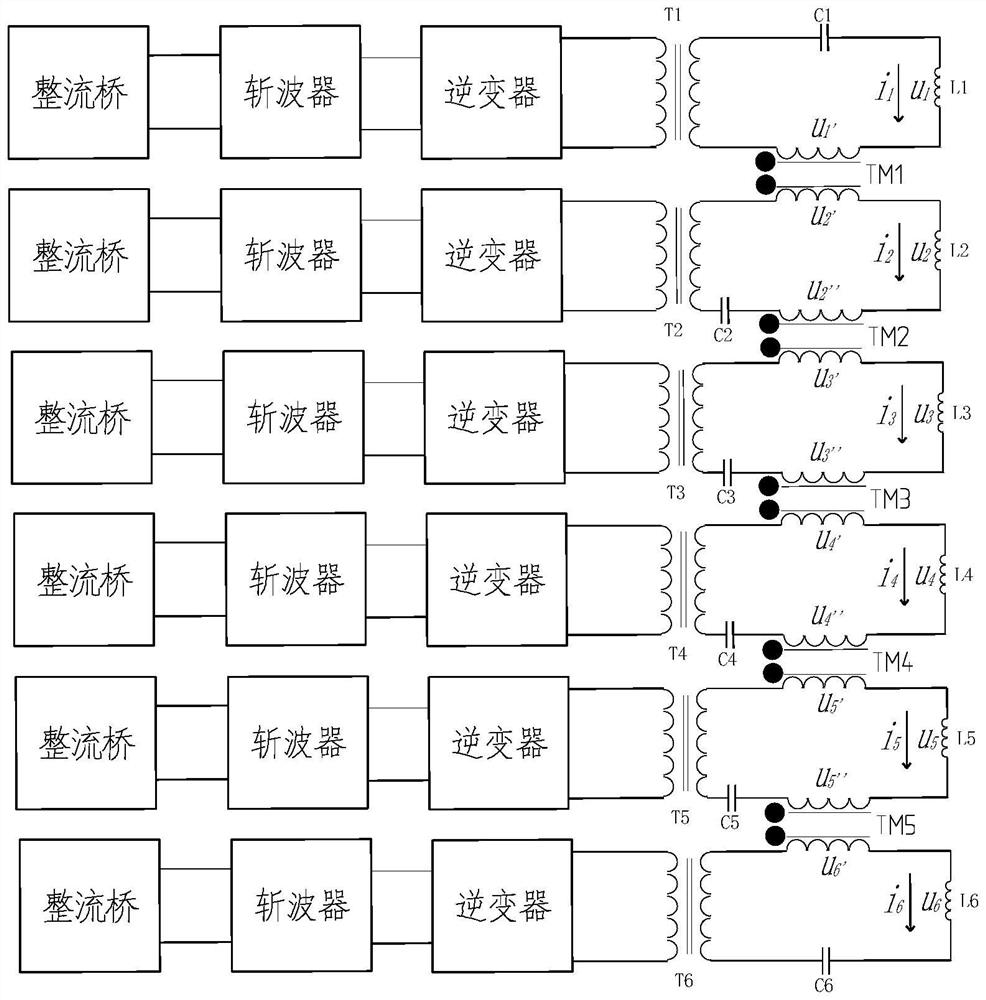
[0016] The embodiment of the invention discloses an induction heating power supply for a multi temperature zone crystal furnace, which comprises: n induction heating power supplies and N-1 coupling transformers TM; Where n is greater than 2, a coupling transformer TM is set between each two induction heating power supplies;

[0017]Each induction heating power supply includes an inverter and a resonant slot circuit. The resonant slot circuit includes a matching transformer T, a resonant capacitor ...


PUM


Abstract

The invention discloses an induction heating power supply for a multi-temperature-zone crystal furnace. The induction heating power supply comprises N induction heating power supplies and N-1 coupling transformers TM, wherein N is greater than 2, and a coupling transformer TM is arranged between every two induction heating power supplies; each induction heating power supply internally comprises an inverter and a resonant tank circuit, the resonant tank circuit comprises a matching transformer T, a resonant capacitor C and an induction coil L, a primary coil of the matching transformer T is connected with the inverter, and two ends of a secondary coil of the matching transformer T are respectively connected with the resonant capacitor C and the induction coil L; and a primary coil and a secondary coil of a coupling transformer TM are respectively connected between the secondary coils and the induction coils L of the two adjacent matching transformers T, so that the electromotive force directions of the two adjacent resonance tank circuits are consistent, and the current directions of the dotted terminals of the coupling transformer TM are opposite. According to the invention, independent power adjustment of a plurality of induction heating power supplies can be realized, and the problem of mutual inductance interference of two adjacent inductors in multi-temperature-zone induction heating application in the prior art is solved.

Description

technical field [0001] The invention relates to the technical field of induction heating, in particular to an induction heating power supply for a multi temperature zone crystal furnace. Background technology [0002] Multi temperature zone heating refers to realizing different temperature adjustment in different areas of the same load. If the induction heating crystal furnace wants to realize multi zone temperature adjustment, it must use multiple induction coils to adjust its heating temperature by adjusting the power on different coils. Induction heating technology makes the load produce eddy current through the magnetic field, so as to make the load heat. However, two adjacent induction coils will produce magnetic field interference, so that they cannot adjust the power alone. [0003] At present, the method used in the industry is to add a closed shielding coil between multiple induction coils and two adjacent induction coils. The purpose is to short circuit the magnetic fie...

Claims


Application Information

Patent Timeline
IPC IPC(8): H05B6/04
CPCH05B6/04
Inventor 柴艳鹏乔玉存王伟恒赵勇付国帅赵文晋
Owner 山西艾德尔电气设备有限公司
Learn More