
Control method for multiple air source heat pump units and air source heat pump system

An air source heat pump and unit technology, which is applied to the control of fluid heaters, fluid heaters, lighting and heating equipment, etc., can solve the problems of unadjustable control, waste of resources, waste of hot water, etc., to save resources and facilitate control , the effect of strengthening control

Pending Publication Date: 2022-05-03
AIRCAL HEAT PUMP LTD
View PDF8 Cites 0 Cited by
  • Summary
  • Abstract
  • Description
  • Claims
  • Application Information

AI Technical Summary

Problems solved by technology

[0003] When the existing air source heat pump units are in use, multiple air source heat pump units are usually operated simultaneously for heating, and cannot be adjusted and controlled according to the water supply demand in different time periods, resulting in less demand for hot water in the time period There are still multiple sets of air source heat pump units running for heating, resulting in waste of resources. At the same time, too much hot water inside the water tank will gradually cool down because it cannot be used in time, which will cause waste of hot water. Therefore, we propose a multi- A control method of an air source heat pump unit and an air source heat pump system

Method used


Image

  • Control method for multiple air source heat pump units and air source heat pump system
  • Control method for multiple air source heat pump units and air source heat pump system
  • Control method for multiple air source heat pump units and air source heat pump system

Examples


Embodiment Construction

[0034] The following will clearly and completely describe the technical solutions in the embodiments of the present invention with reference to the accompanying drawings in the embodiments of the present invention. Obviously, the described embodiments are only some, not all, embodiments of the present invention. Based on the embodiments of the present invention, all other embodiments obtained by persons of ordinary skill in the art without making creative efforts belong to the protection scope of the present invention.

[0035] The embodiment of the invention discloses an air source heat pump system of multiple air source heat pump units.

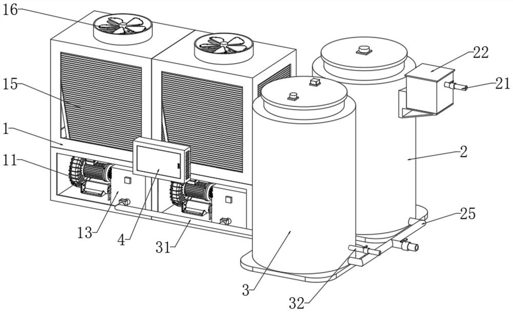
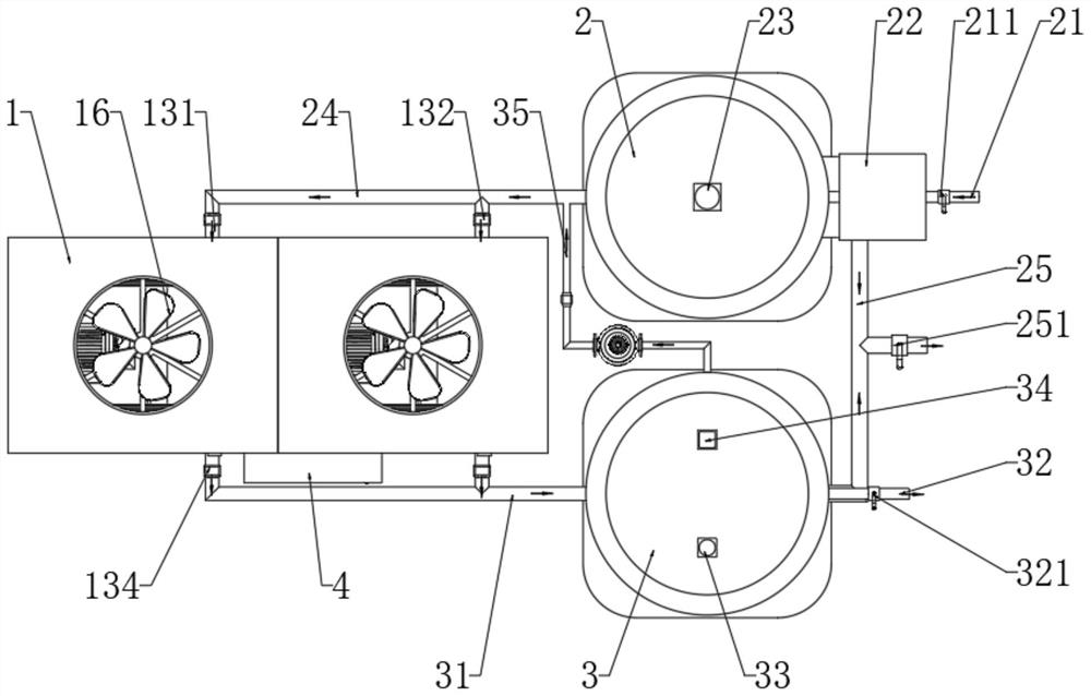
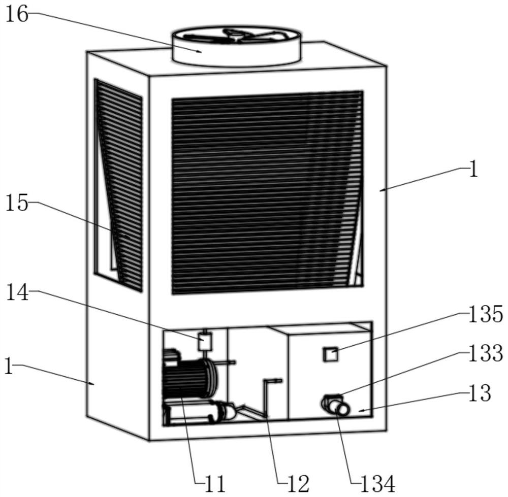
[0036] According to attached figure 1 And attached figure 2 As shown, it includes a plurality of air source heat pump units. The air source heat pump unit includes a cabinet 1. A compressor 11 is installed inside and near the bottom of the cabinet 1. A condensation box 13 is provided on the right side of the compressor 11. Above the compr...


PUM


Abstract

The invention discloses a control method for multiple air source heat pump units and an air source heat pump system.The air source heat pump system comprises the multiple air source heat pump units, each air source heat pump unit comprises a machine cabinet, a compressor, a condensation box, a fin evaporator and a fan are installed in the machine cabinet, a tap water tank is arranged on the right side of each air source heat pump unit, and a water outlet is formed in the right side of the corresponding air source heat pump unit. A heat preservation water tank is arranged on the front side of the tap water tank, a control cabinet is arranged on the front side of the air source heat pump unit, and a controller is arranged in the control cabinet. The air source heat pump system has the beneficial effects that the controller can adjust and control the air source heat pump units according to the hot water demanded quantity in different time periods, the situation that multiple air source heat pump units operate at the same time in the time period with the small hot water demanded quantity is avoided, and therefore energy waste is reduced, and the hot water supply effect is improved.

Description

technical field [0001] The invention relates to a control method of multiple air source heat pump units and an air source heat pump system, in particular to a control method of multiple air source heat pump units and an air source heat pump system, belonging to the technical field of air source heat pumps. Background technique [0002] Air source heat pump is an energy-saving device that uses high-level energy to make heat flow from low-level heat source air to high-level heat source. It has the advantages of safety, energy saving and high heating efficiency. [0003] When the existing air source heat pump units are in use, multiple air source heat pump units are usually operated simultaneously for heating, and cannot be adjusted and controlled according to the water supply demand in different time periods, resulting in less demand for hot water in the time period There are still multiple sets of air source heat pump units running for heating, resulting in waste of resource...

Claims


Application Information

Patent Timeline
Patent Type & Authority Applications(China)
IPC IPC(8): F24H4/02F24H9/1809F24H9/20F24H15/223F24H15/375
CPCF24H4/02F24H9/1809F24H9/2007
Inventor 蒋崇军伍兆海
Owner AIRCAL HEAT PUMP LTD
Learn More