Reciprocating shaking type building construction sand screening mechanism with dust suction function
A technology of construction and function, applied in the fields of sieving, cleaning methods and utensils, solid separation, etc., can solve the problems of reducing sand sieving efficiency, properties and unsatisfactory effects, and achieve the effect of ensuring the on-site environment of sand sieving
- Summary
- Abstract
- Description
- Claims
- Application Information
AI Technical Summary
Problems solved by technology
Method used
Image

Examples
Embodiment 1
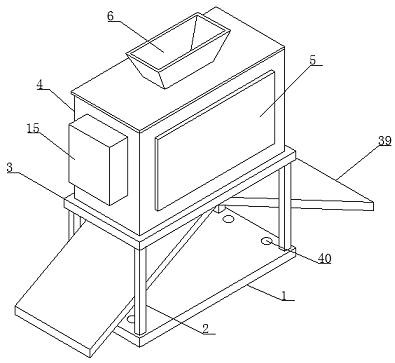
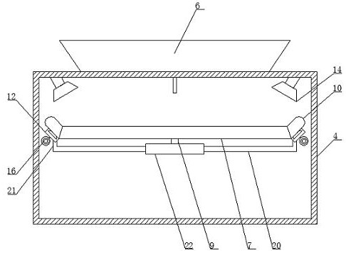
[0032] Such as Figure 1-7 As shown, according to the embodiment of the present invention, the reciprocating shaking type construction sand screening mechanism with dust suction function includes a bottom plate 1 and a frame 2 positioned at the top of the bottom plate 1, and the top of the top frame 2 is provided with a supporting plate 3 , the top of the supporting plate 3 is provided with a housing 4, and one side opening of the housing 4 is provided with a cover plate 5, and the cover plate 5 is connected with the housing 4 through a hinge, and the housing 4 The top of the top is provided with a feed funnel 6, and the housing 4 is provided with a horizontally arranged screen frame 7, the screen frame 7 is provided with a matching screen 8, the bottom of the screen 8 The end is provided with an L-shaped strut 9
[0033] The L-shaped strut 9 is connected to the shaking assembly located in the housing 4, and the two sides of the screen frame 7 are respectively provided with c...
Embodiment 2
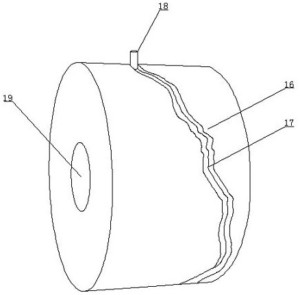
[0035] Such as Figure 1-7 As shown, the reciprocating assembly includes a rotating cylinder 16 located in the housing 4, the outer wall of the rotating cylinder 16 is surrounded by an arc-shaped chute 17 inclined from left to right, and the movable block 12 The bottom end is provided with the sliding column 18 that matches with described arc-shaped chute 17, and described arc-shaped chute 17 is coated with lubricating oil one, and one side in described slideway 13 is provided with electric telescopic rod 41, so One end of the electric telescopic rod 41 is connected with the trapezoidal slider 11, the slideway 13 is coated with lubricating oil, the housing 4 is provided with a drive motor 19, and the output end of the drive motor 19 is connected to the The rotating cylinders 16 are connected.
Embodiment 3
[0037] Such as Figure 1-7As shown, the reciprocating assembly includes a U-shaped frame 20 located below the screen 8, and the two sides of the top of the U-shaped frame 20 are provided with brackets 21 connected to the movable block 12. The U-shaped frame 20 is provided with a casing 22, the casing 22 is provided with a servo motor 23, the output end of the servo motor 23 is provided with a cam sheet 24, and one end of the cam sheet 24 is provided with an arc sheet 25, the The arc sheet 25 is connected with the cam sheet 24 by a movable shaft one 26, and a bottom end of one side of the arc sheet 25 is provided with a vertically arranged push-pull rod 27, and the top end of the push-pull rod 27 extends to the In the cylindrical body 28 at the top end of the casing 22, the cylindrical body 28 is a cavity structure with an open bottom end, and a piston block 29 matching it is arranged in the cylindrical body 28, and the bottom end of the piston block 29 is provided with There ...
PUM
 Abstract
Description
Claims
Application Information
 - R&D
- Intellectual Property
- Life Sciences
- Materials
- Tech Scout
- Unparalleled Data Quality
- Higher Quality Content
- 60% Fewer Hallucinations
Browse by: Latest US Patents, China's latest patents, Technical Efficacy Thesaurus, Application Domain, Technology Topic, Popular Technical Reports.
© 2025 PatSnap. All rights reserved.Legal|Privacy policy|Modern Slavery Act Transparency Statement|Sitemap|About US| Contact US: help@patsnap.com