Pneumatic drill jig capable of being quickly assembled and disassembled

A jig-drilling and fast technology, applied in the direction of the jig-drilling used for the workpiece, etc., can solve the problems of high man-hour cost of machine tools, time-consuming turning and positioning, and uneconomical cost, etc., to achieve convenient clamping, good product consistency, and clamping Convenient and reliable effect

Pending Publication Date: 2022-05-06
苏州伊徕尔特机械有限公司
View PDF0 Cites 0 Cited by
  • Summary
  • Abstract
  • Description
  • Claims
  • Application Information

AI Technical Summary

Problems solved by technology

[0002] At present, for the end faces of rotary parts that are not in the center of rotation, most of them are completed by machining centers or multi-axis turning-milling compound processing machines, or by using traditional drilling molds and bench drills. The first two methods have higher requirements for machine tools. , the cost of machine tool man-hours is high, and the cost is very uneconomical
Traditional drilling jigs are used for processing, and the clamping of products and the flipping and positioning of drilling jigs are time-consuming and inefficient.

Method used


Image

  • Pneumatic drill jig capable of being quickly assembled and disassembled

Examples


Embodiment 1

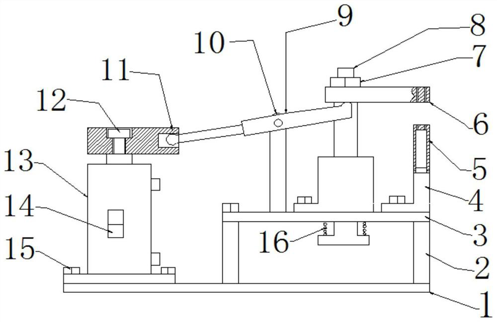
[0037] This embodiment provides a pneumatic fast loading and unloading drilling mold, its structure is as follows figure 1 As shown, it includes a clamp body 1, a support base 3 fixed on the clamp body 1, a positioning support 4 and a movable support rod 8 arranged on the support base 3, and a drilling template 6, and the top of the positioning support 4 is placed to be processed. The workpiece 5, the movable support rod 8 has a degree of freedom to move in the direction perpendicular to the support seat 3, the drilling template 6 is fixedly installed on the top of the movable supporting rod 8, and the drilling template 6 is also processed with a drilling template guide hole facing the workpiece 5 .

[0038] see you again figure 1 As shown, the support base 3 is arranged on the clamp body 1 through the support plate 2, and a space is reserved between the support base 3 and the clamp body 1, so that the movable support rod 8 can be conveniently moved on the support base 3 alon...


PUM


Abstract

The invention relates to a pneumatic quick assembly and disassembly drill jig which comprises a jig body, a supporting base fixed to the jig body, a positioning support, a movable supporting rod and a drill jig plate, the positioning support and the movable supporting rod are arranged on the supporting base, a workpiece to be machined is placed on the top of the positioning support, and the movable supporting rod has the freedom degree of moving in the direction perpendicular to the supporting base. The drill plate is fixedly installed on the top of the movable supporting rod, and a drill plate guide hole right opposite to a workpiece is further machined in the drill plate. Compared with the prior art, workpieces are convenient to assemble and disassemble, the clamping quality is stable and efficient, and the positioning precision is high.

Description

technical field [0001] The invention belongs to the technical field of numerically controlled machining of key components, and relates to a pneumatic fast loading and unloading drilling mold. Background technique [0002] At present, for the end faces of rotary parts that are not in the center of rotation, most of them are completed by machining centers or multi-axis turning-milling compound processing machines, or by using traditional drilling molds and bench drills. The first two methods have higher requirements for machine tools. , the cost of machine tool man-hours is high, and the cost is very uneconomical. Traditional drilling jigs are used for processing, and the clamping of products and the flipping and positioning of drilling jigs are time-consuming and inefficient. Contents of the invention [0003] The object of the present invention is to provide a pneumatic fast loading and unloading drilling mold, so as to realize fast and high-quality clamping of workpieces...

Claims


Application Information

Patent Timeline
Patent Type & Authority Applications(China)
IPC IPC(8): B23B47/28
CPCB23B47/28B23B2247/12
Inventor 秦国军王招生卢贵慧高春林
Owner 苏州伊徕尔特机械有限公司
Why Eureka
Try Eureka