[0037] The following description is merely exemplary and is not intended to limit the present disclosure, application or use. It should be understood that in the drawings, the corresponding reference numerals represent similar or corresponding parts and features.
[0038] Hereinafter, an exemplary form of hybrid air mobile aircraft of the present disclosure will be described with reference to the accompanying drawings.
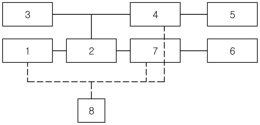
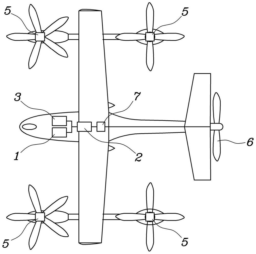
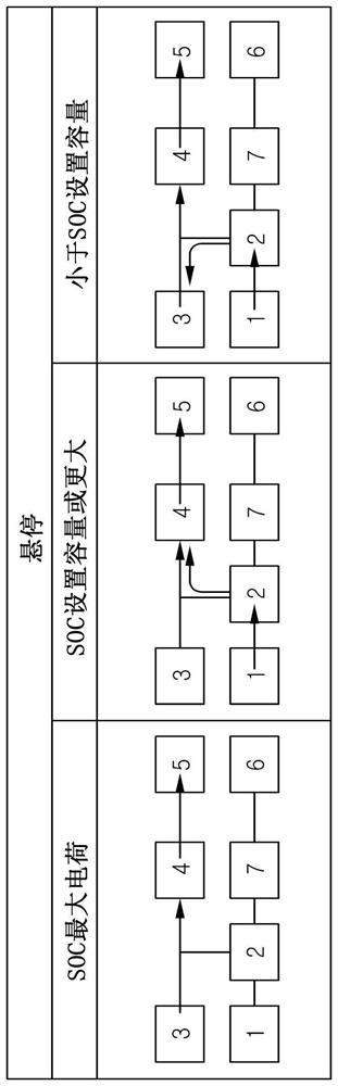
[0039] Figure 1 Is a configuration diagram of a hybrid air mobile aircraft according to a form of the present disclosure, Figure 2 Is shown Figure 1 Figure of the hybrid air mobile vehicle shown in, Figure 3 and Figure 4 It's a description Figure 1 The hovering control diagram of the hybrid air mobile vehicle shown in, Figure 5 It's a description Figure 1 A diagram of the control of the hybrid air mobile vehicle during cruise in hover is shown, Figure 6 and Figure 7 It's a description Figure 1 A diagram of the cruise control of the hybrid air mobile vehicle shown in, and Figure 8 It's a description Figure 1 Figure of taxiing control of hybrid air mobile vehicle shown in.
[0040] as Figure 1 As shown, a hybrid air mobile vehicle in one form of the present disclosure includes an engine 1 and a generator 2, a battery 3 and a drive motor 4 electrically connected to the generator 2, a first propeller 5 electrically connected to the drive motor 4 and a second propeller 6 electrically connected to the generator 2 through a clutch 7, and a controller 8 configured to control the drive of the engine 1, the clutch 7 and the drive motor 4 and based on a flight mode The drive is controlled by the required power, battery charge and one or more flight factors in the surrounding flight environment.
[0041] Here, the engine 1 is an internal combustion engine that generates power by burning fuel, and the battery 3 stores electric energy therein.
[0042] The generator 2 receives the power generated and transmitted from the engine 1 and generates power, or is driven by the power transmitted from the battery 3 and operates the second propeller 6 by generating rotating power. Specifically, the generator 2 is connected to the second propeller 6 via the clutch 7, and the rotating power of the generator 2 is selectively transmitted to the second propeller 6 according to whether the clutch 7 is engaged or not.
[0043] The drive motor 4 is supplied with power from the battery 3 or power generated and transmitted from the generator 2, and operates the first propeller 5.
[0044] The configuration of engine 1, generator 2, battery 3, clutch 7 and controller 8 as described above is provided in the flight body, and the first propeller 5 and the second propeller 6 are installed outside the flight body to generate thrust. Here, for the first propeller 5 and the second propeller 6, for example Figure 2 As shown, a plurality of first propellers 5 are arranged on the wing of the flight body to generate upward and downward thrust during takeoff and landing of the flight body, and a second propeller 6 is arranged on the wing or tail of the flight body to generate backward thrust during flight of the flight body.
[0045] That is, if Figure 2 A plurality of propellers are arranged on the wing 5 for generating the lift force in the first direction of flight. The first propeller 5 is driven during takeoff and landing of the flight body and generates thrust, so that the flight body moves upward. At the same time, the second propeller 6 is arranged on the wing or tail of the flight body and generates thrust backward to make the flight body move forward. The second propeller 6 described above can be applied to the tail of the flying body and can make the flying body fly forward.
[0046] Thus, the flight body according to the present disclosure is a hybrid type using the power of the battery 3 or the power driven by the engine 1, and can fly by the drive of the first propeller 5 and the second propeller 6.
[0047] Specifically, the controller 8 controls the drive of the engine 1, the clutch 7 and the drive motor 4, and controls the drive based on one or more flight factors including flight mode, required power, battery charge and the surrounding flight environment. As described above, the controller 8 controls the driving of the engine 1, the clutch 7 and the drive motor 4 based on various flight factors, and therefore can optimize the flight according to their respective conditions.
[0048] In one form, the controller 8 may implement a flight mode including hovering, cruising or taxiing, and determine the required power according to the flight speed required during hovering or cruising. Here, hovering corresponds to the case that the flying body moves or hovers in the upward and downward directions, cruise corresponds to the case that the flying body flies in the forward and backward directions towards a specific position, and taxiing corresponds to the case that the flying body moves when the flying body lands on the ground. In addition, the controller 8 determines whether to use the power of the battery 3 or the power of the engine 1 by determining the required power according to the flight speed.
[0049] At the same time, the surrounding flight environment includes the population density of the flight area, whether there is a safety zone in the flight area, the presence / absence of noise blocking facilities, and the flight altitude. Such surrounding flight environment information can be collected through satellite information. As described above, the controller 8 controls that the noise generated from the flight of the flight subject is reduced according to the surrounding conditions based on the collected information such as the population density of the flight area, the presence / absence of a safety zone in the flight area, the presence / absence of noise blocking facilities, and the flight altitude.
[0050] Based on this, the controller 8 effectively distributes and uses the power of the battery and the power of the engine 1 considering the flight mode, the battery charge and the surrounding flight environment.
[0051] More specifically, such as Figure 3As shown, when the flight mode is hovering and the battery charge is in the maximum charge state, the controller 8 operates the first propeller 5 by driving the drive motor 4 with the power of the battery 3. As described above, during the hover of the flight body, the battery charging amount is in the maximum charging state, and if the driving motor 4 is driven only by the power of the battery 3, the flight noise is reduced. That is, the drive motor 4 generates very little drive noise during its operation, and therefore discomfort caused by flight noise does not occur during hovering of the flight body. However, the flying body uses a large power during hovering, and when the battery charging amount is in the maximum charging state, the first propeller 5 is operated only by driving the driving motor 4 by the power of the battery 3. Here, the maximum charging state of the battery charging amount can be set so that the remaining amount is equal to or greater than 90%.
[0052] At the same time, when the flight mode is hovering and the battery charge is equal to or greater than the set capacity, the controller 8 drives the drive motor 4 to operate the first propeller 5 by using the power generated by the generator 2 through the drive of the engine 1 and the power of the battery 3. As described above, if the battery charging amount is equal to or greater than the set capacity during the hover of the flight body, the generator 2 generates power according to the driving power of the engine 1, and the driving motor 4 is driven together with the corresponding power through the power of the battery 3, so as to reduce the consumption of electric energy stored in the battery 3. Here, the setting capacity of the battery charging amount can be set so that the remaining amount is equal to or greater than 20%. That is, during the hover of the flight body, a large power is used, and if the drive motor 4 is driven only by the power of the battery 3 when a part of the battery charge is consumed, the power stored in the battery 3 may be in an excessive consumption state. Therefore, if the battery charging amount is equal to or greater than the set capacity in the hovering state, the controller 8 operates the first propeller 5 by driving the drive motor 4 with the power generated from the generator 2 and the power of the battery 3.
[0053] At the same time, such as Figure 4 As shown, when the population density in the flight area is equal to or higher than the reference population and the flight altitude is equal to or lower than the set altitude, the controller 8 operates the first propeller 5 by driving the drive motor 4 with the power of the battery 3. That is, if the population density is equal to or higher than the reference population, discomfort may be generated for the flight noise in the corresponding residence. Specifically, if the flying altitude of the flying body is low, a large flying noise is transmitted around. Therefore, if the population density of the flight area is equal to or higher than the reference population and the flight altitude is equal to or lower than the set altitude, the controller 8 uses the power of the battery 3 to drive the drive motor 4 to reduce the flight noise. Here, if the flight altitude is equal to or higher than the set altitude, the controller 8 drives the drive motor 4 to operate the first propeller 5 by using the power generated from the generator 2 driven by the engine 1 and the power of the battery 3.
[0054] At the same time, when there is a noise blocking facility in the flight area, the controller 8 drives the drive motor 4 to operate the first propeller 5 by using the power generated by the generator 2 through the drive of the engine 1 and the power of the battery 3. Here, the noise blocking facility can be a vertical airport, and if there is a noise blocking facility although the population density is equal to or higher than the reference population, the noise blocking facility blocks the surrounding noise, so the problem of noise generation can be solved.
[0055] In addition, when the flight area is a safe area, the controller 8 drives the drive motor 4 to operate the first propeller 5 by using the power generated by the generator 2 through the drive of the engine 1 and the power of the battery 3. Here, a safety zone may be an area in which noise problems do not occur, such as a non residential area or an airport.
[0056] As described above, if the noise blocking facility exists in the flight area or the flight area is a safe area, the controller 8 drives the drive motor 4 by using the power generated by the generator 2 through the drive of the engine 1 and the power of the battery 3, and therefore the power consumption of the battery 3 can be reduced.
[0057] As described above, during hovering flight, the use efficiency of electric energy of battery 3 is improved by selectively using the drive of engine 1 or the power of battery 3 according to the battery charge, and the discomfort caused by surrounding flight noise can be solved by selectively using the drive of engine 1 considering the surrounding flight environment.
[0058] At the same time, when the flight mode is hovering and the battery charging amount is less than the set capacity, the controller 8 uses the power generated by the generator 2 through the drive of the engine 1 to charge the battery 3 and drive the drive motor 4. When the abnormal charging amount of the driving battery 3 is controlled by the controller as described above, when the abnormal charging amount of the driving battery 3 is also generated by the control of the driving motor 3, not only when the abnormal charging amount of the driving battery 3 occurs, but also when the abnormal charging amount of the driving battery 3 occurs. For this purpose, the controller 8 can control to increase the output according to the drive of the engine 1, and operate the first propeller 5 by using the power generated by the generator 2 through the drive of the engine 1, so as to ensure flight stability.
[0059] Hereinafter, the cruise control according to hovering when the flight subject enters a predetermined altitude will be described.
[0060] as Figure 5 As shown, when the flight mode is hovering cruise and the battery charging amount is in the maximum charging state, the controller 8 operates the first propeller 5 and the second propeller by driving the driving motor 4 and the generator 2 with the power of the battery 3 and meshing the clutch 7. That is, since the flight subject changes flight through hovering cruise, the controller 8 operates the first propeller 5 and the second propeller 6 together. For this purpose, the controller 8 transmits the rotational power of the generator 2 to the second propeller 6 through the tooth engagement clutch 7.
[0061] In addition, if the battery charging amount is in the maximum charging state, the controller 8 drives the driving motor 4 only with the power of the battery 3 to reduce the flight noise. Such control of the controller 8 can be performed even when the operation of the engine 1 is impossible.
[0062] At the same time, the controller 8 determines whether to save the battery according to the battery charging amount. In this case, the battery charging amount may be equal to or greater than the set capacity. Here, the controller 8 can determine whether to save the battery by deriving the power consumption of the battery 3 according to the flight distance of the flight body and the remaining amount of battery charging, which is an element for determining whether to perform battery saving. As described above, if it is desired to save the battery, the controller 8 operates the first propeller 5 by driving the drive motor 4 with the power of the battery 3, and drives the engine 1 through the tooth engagement clutch 7 to operate the second propeller 6. That is, in the case of changing from hovering to cruising, the first propeller 5 and the second propeller 6 should be driven. In this case, the first propeller 5 is driven by transmitting the power of the battery 3 to the drive motor 4, and the second propeller 6 is driven by the transmitted power according to the drive of the engine 1, thereby reducing the power consumption of the battery 3.
[0063] In addition, the controller 8 subdivides the battery saving according to the battery charging amount, and with the reduction of the battery charging amount, drives the driving motor 4 by increasing the output according to the driving of the engine 1, or charges the battery 3 with the power generated by the generator 2. As described above, when the battery charging amount decreases, the controller 8 drives the second propeller 6 and charges the battery 3 by increasing the output according to the driving of the engine 1. Therefore, even if the battery 3 consumes power according to the operation of the first propeller 5, it can be charged through the engine 1 and the generator 2, so the power consumption of the battery 3 is reduced.
[0064] As described above, during the transition flight from hover to cruise, the controller 8 operates the first propeller 5 and the second propeller 6, and performs battery saving control according to the battery charging amount, so the power consumption of the battery 3 is reduced, making long-distance flight possible.
[0065] Hereinafter, the cruise control according to the flight subject will be described.
[0066] as Figure 6As shown, when the flight mode is cruise and the battery charge is equal to or greater than the set capacity, the controller 8 operates the second propeller 6 by engaging the clutch 7 and driving the generator 2 with the power of the battery 3. As described above, if the battery charging amount is equal to or greater than the set capacity during the cruise of the flight body, the second propeller 6 is operated by the generator 2 only using the power of the battery 3 to reduce the flight noise. That is, since a very small driving noise occurs by rotating the second propeller 6 through the generator 2 using the power of the battery 3, the discomfort of passengers caused by the flight noise during cruise flight is reduced. In addition, since the flying body can fly through the lift, the operation amount of the second propeller 6 is reduced compared with hovering. If the power of the second controller 6 is greater than or equal to the charging amount of the battery 3 during cruise operation, therefore, if the charging amount of the second controller 6 is greater than or equal to the charging amount of the battery.
[0067] Meanwhile, when the flight mode is cruise, the battery charge is equal to or greater than the set capacity, and the flight speed is equal to or greater than the high driving speed, the controller 8 engages the clutch 7 through the teeth and drives the engine 1, and uses the power of the battery 3 and the driving power of the engine 1 to operate the second propeller 6. Here, according to the flight speed, the high driving speed can be determined according to the power consumption of battery 3. If the flight subject performs high-speed drive in the state of cruise in the flight mode, the required power increases, and in this case, if the second propeller 6 is operated only with the power of battery 3, the power consumption of battery 3 accelerates. Therefore, when the flying body flies at a high driving speed, the controller 8 uses the power of the battery 3 to operate the second propeller 6 together with the power driven by the engine 1, thereby reducing the power consumption of the battery 3.
[0068] Here, such as Figure 7 As shown, the controller 8 determines whether to save the battery according to the amount of battery charge, and when it is desired to save the battery, drives the power of the engine 1 by engaging the clutch 7 and driving the engine 1 to operate the second propeller 6. The controller 8 can determine whether to save the battery by deriving the power consumption of the battery 3 according to the flight distance of the flight body and the remaining amount of battery charging, which is an element for determining whether to perform battery saving. As described above, if battery saving is desired in the cruise flight state, the controller 8 operates the second propeller 6 using the power by driving the engine 1. Thus, the second propeller 6 is driven by the power transmitted by the drive of the engine 1, and since the power of the battery 3 is not used, the flight distance through the battery 3 can be ensured thereafter.
[0069] At the same time, when the population density is equal to or higher than the reference population or the flight altitude is equal to or lower than the set altitude, the controller 8 engages the clutch 7 through the teeth and uses the power of the battery 3 to drive the generator 2 to operate the second propeller 6. As described above, if the population density of the flight area is equal to or higher than the reference population and the flight altitude is equal to or lower than the set altitude, the controller 8 can be controlled by the operation of the second propeller 6 according to the drive of the generator 2 using the power of the battery 3 to reduce the flight noise. Thus, the occurrence of ambient noise damage caused by the flight of the flight subject can be prevented.
[0070] At the same time, when the flight mode is cruise, the battery charging amount is less than the set capacity, or in the case of emergency landing, the controller 8 operates the second propeller 6 through the tooth engagement clutch 7, and uses the power generated by the generator 2 to charge the battery 3 by increasing the output according to the drive of the engine 1. Here, emergency landing is the case of engine failure, component failure and flight accident. As described above, if the battery charging amount is less than the set capacity, or in the case of emergency landing, an abnormality may occur not only when controlling the propeller according to flight, but also when controlling the main power. In this case, the controller 8 uses the power generated by the generator 2 through the drive of the engine 1 to charge the battery 3 and operate the second propeller 6 at the same time. In this case, the controller 8 controls to increase the output according to the drive of the engine 1, and smoothly performs the power charging of the battery 3 and the operation of the second propeller 6 through the drive of the engine 1.
[0071] At the same time, such as Figure 8 As shown, when the flight mode is taxi, the controller 8 operates the second propeller 6 by engaging the clutch 7 and driving the generator 2 with the power of the battery 3. That is, if the flight mode is taxiing, the flight body operates on the ground, and the flight noise can be reduced by operating the second propeller 6 through the generator 2 using the power of the battery 3. If the flight body is provided with a landing wheel, taxiing can be performed through the landing wheel, and if it is impossible to move through the landing wheel or additional power is required, the flight body can be moved through the operation of the second propeller 6.
[0072] Meanwhile, when the flight mode is taxi and the battery charge is less than the set capacity, the controller 8 drives the engine 1 and operates the second propeller 6 using the power generated by the drive of the engine 1. Thus, even if the battery charge is less than the set capacity, the flight body can move by using the driving power of the engine 1 through the operation of the second propeller 6, and supply power to the main power supply in addition to the control required for the movement of the second propeller 6. Therefore, this paper can perform stable operation.
[0073] The hybrid air mobile vehicle composed of the above structure can fly for a long distance through the effective driving of engine 1 and battery 3, and reduce the discomfort caused by noise by reducing noise according to the flight environment.
[0074] Although the specific form of the present disclosure has been described and described for illustrative purposes, those skilled in the art will understand that various modifications, additions and substitutions can be made without departing from the technical ideas of the present disclosure.