Water insulation cup for electronic water pump and electronic water pump

An electronic water pump and water cup technology, which is applied to the components, pumps, and pump components of the pumping device for elastic fluids, can solve the problems of controller damage, high temperature of the controller without heat dissipation, etc., and achieves high reliability.

Pending Publication Date: 2022-05-06
HUNAN OIL PUMP
View PDF0 Cites 0 Cited by
  • Summary
  • Abstract
  • Description
  • Claims
  • Application Information

AI Technical Summary

Problems solved by technology

[0002] Existing electronic water pumps generally include a water separator, a rotor assembly, a stator assembly, a controller, and a rear cover. When the electronic water pump is powered on, the controller continues to work, and the electronic components in the controller continue to generate heat, which in turn makes the temperature of the controller Gradually increase, when the temperature is higher than the temperature that the electronic components can withstand, the controller will be damaged, and the electronic water pump will stop running. The above-mentioned water separator is set between the rotor assembly and the stator assembly, and only plays the role of dry and wet separation. No cooling effect on the high temperature of the controller

Method used


Image

  • Water insulation cup for electronic water pump and electronic water pump
  • Water insulation cup for electronic water pump and electronic water pump

Examples


Embodiment approach

[0019] In order to make the technical problems, technical solutions and advantages to be solved by the present invention clearer, the following will describe in detail with reference to the drawings and specific embodiments. In the following description, characteristic details such as specific configurations and components are provided only to help a comprehensive understanding of the embodiments of the present invention. Accordingly, those of ordinary skill in the art should recognize that various changes and modifications of the embodiments described herein can be made without departing from the scope and spirit of the invention. Also, descriptions of well-known functions and constructions are omitted for clarity and conciseness.

[0020] It should be understood that reference throughout this specification to "one embodiment" or "an embodiment" means that a particular feature, structure, or characteristic related to the embodiment is included in at least one embodiment of th...

Embodiment 1

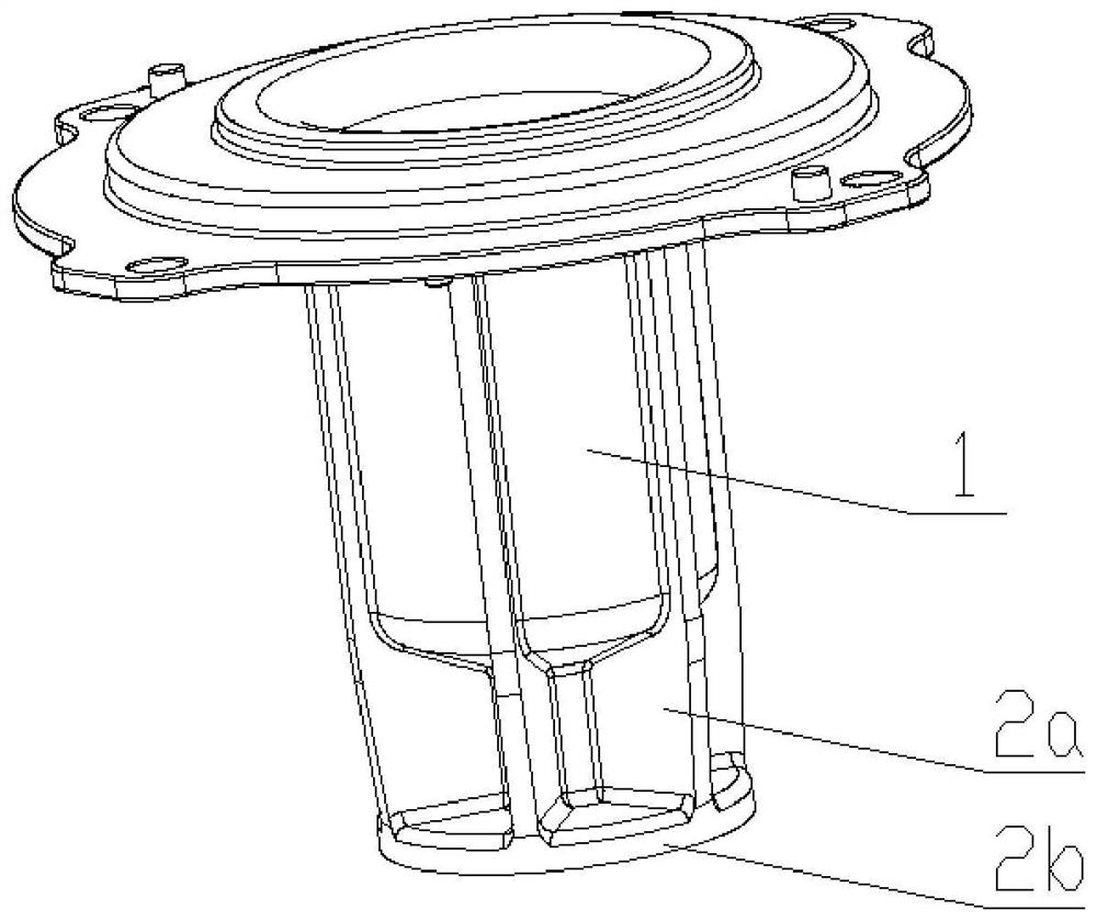
[0026] Such as figure 1 As shown, this embodiment includes a water separator 1, a circular boss 2b extends from the bottom of the water separator 1, a hollow 2a is formed between the circular boss 2b and the bottom of the water separator 1, and the surface of the circular boss 2b is set There is a heat-dissipating silicone layer; specifically, in this embodiment, the circular boss 2b and the water-separating cup 1 are integrally formed, and the upper end of the water-separating cup 1 is open and semi-closed.

Embodiment 2

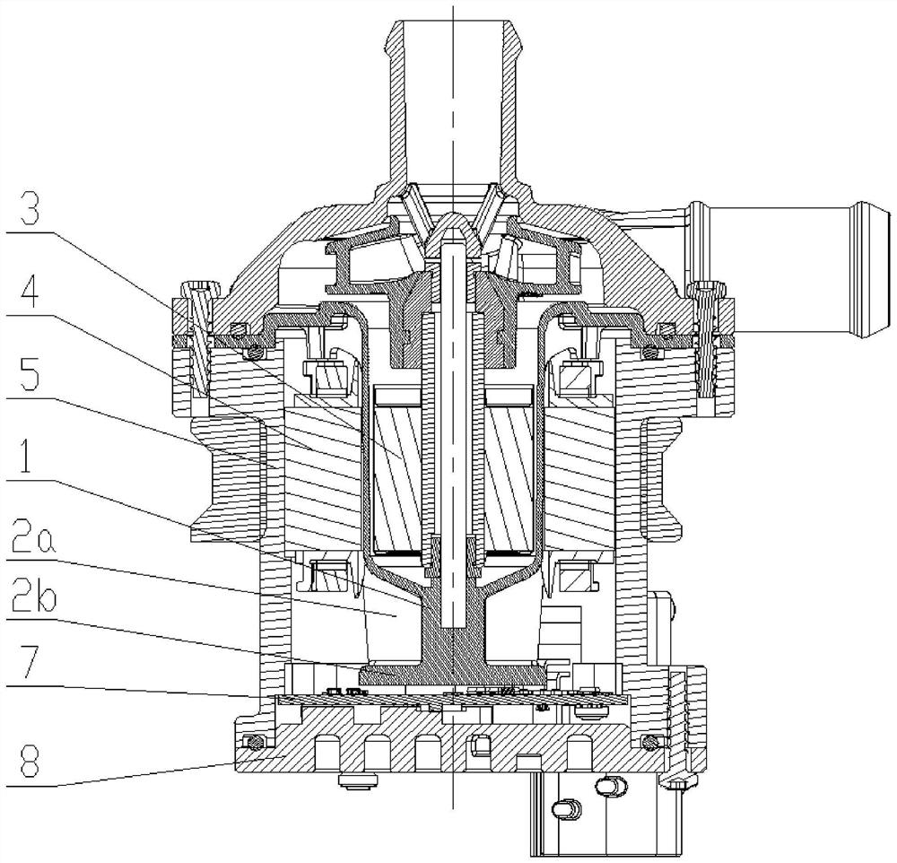
[0028] Such as figure 2 As shown, this embodiment includes a water-proof cup 1, a rotor assembly 3, a stator assembly 4, a pump body 5, a controller 7, and a rear cover 8, wherein the water-proof cup 1 is arranged in the pump body 5, and the rotor assembly 3 is arranged in the water-proof cup 1, the stator assembly 4 is arranged between the water separator cup 1 and the pump body 5, the controller 7 is arranged on the back cover 8 and is located under the water separator cup 1, further, the rear cover 8 is located under the pump body 5 and is connected to the pump body 5 fixed connection; specifically, the bottom of the water separator cup 1 is close to the controller 7; thus, when in use, the surface of the circular boss 2b passing through the bottom of the water separator cup 1 is coated with a heat-dissipating silicone layer, and the circular boss The heat-dissipating silicone layer on the surface of 2b is close to the heat-dissipating components of the controller 7. When ...


PUM


Abstract

According to the water insulation cup for the electronic water pump and the electronic water pump, the bottom of the water insulation cup for the electronic water pump extends to form a circular boss, a hollow shape is formed between the circular boss and the bottom of the water insulation cup, and a heat dissipation silica gel layer is arranged on the surface of the circular boss; the electronic water pump comprises a water insulation cup, a rotor assembly, a stator assembly, a pump body, a controller and a rear cover, the water insulation cup is arranged in the pump body, the rotor assembly is arranged in the water insulation cup, the stator assembly is arranged between the water insulation cup and the pump body, and the controller is arranged on the rear cover and located below the water insulation cup. The surface of the circular boss at the bottom of the water insulation cup is coated with the heat dissipation silica gel layer, and the heat dissipation silica gel layer on the surface of the circular boss is tightly attached to the controller heat dissipation component, so that heat generated by the controller component in continuous work is conducted into the hollow cavity formed between the bottom of the water insulation cup and the circular boss through the heat dissipation silica gel layer on the circular boss; and heat can be quickly and efficiently dissipated through the hollow cavity, so that the purpose of cooling is achieved.

Description

technical field [0001] The invention relates to the technical field of heat dissipation of an electronic water pump, in particular to a water-proof cup used for the electronic water pump and the electronic water pump. Background technique [0002] Existing electronic water pumps generally include a water separator, a rotor assembly, a stator assembly, a controller, and a rear cover. When the electronic water pump is powered on, the controller continues to work, and the electronic components in the controller continue to generate heat, which in turn makes the temperature of the controller Gradually increase, when the temperature is higher than the temperature that the electronic components can withstand, the controller will be damaged, and the electronic water pump will stop running. The above-mentioned water separator is set between the rotor assembly and the stator assembly, and only plays the role of dry and wet separation. There is no cooling effect on the high temperatur...

Claims


Application Information

Patent Timeline
Patent Type & Authority Applications(China)
IPC IPC(8): F04D29/58
CPCF04D29/5813F04D29/5806F04D13/06H02K7/14H02K11/30H05K7/2039
Inventor 阳波许仲秋刘光明佘笑梅
Owner HUNAN OIL PUMP
Why Eureka
Try Eureka