Supercharge Your Innovation With Domain-Expert AI Agents!

Method for determining power compensation value of optical signal and related device

A power compensation and optical signal technology, applied in the field of optical communication, can solve problems such as exceeding the bearing capacity, reducing the stability of signal transmission, complex changes in power transfer, etc., and achieve the effect of improving stability

Pending Publication Date: 2022-05-06
HUAWEI TECH CO LTD
View PDF0 Cites 4 Cited by
  • Summary
  • Abstract
  • Description
  • Claims
  • Application Information

AI Technical Summary

Problems solved by technology

When adding or dropping waves, the number, distribution, and position of multi-wavelength signals will change randomly, resulting in complex changes in power transfer between multi-wavelength signals, which may exceed the system's ability to withstand, thereby reducing Stability of signal transmission

Method used

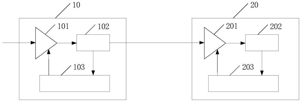
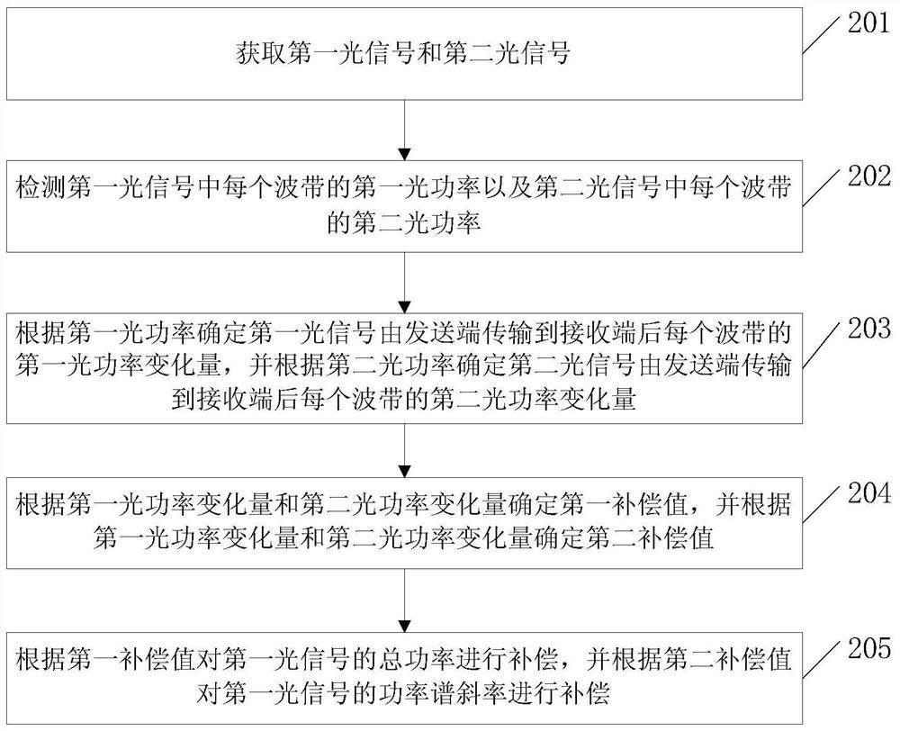

Image

  • Method for determining power compensation value of optical signal and related device
  • Method for determining power compensation value of optical signal and related device
  • Method for determining power compensation value of optical signal and related device

Examples


Embodiment Construction

[0039] The embodiment of the present application provides a method and a related device for determining the power compensation value of an optical signal, so that the power change caused by the SRS effect during the transmission of the optical signal in the optical fiber will not exceed the capacity of the system, and the optical signal will not exceed the capacity of the system. The slope of the power spectrum before and after wave or drop is matched, which improves the stability of signal transmission.

[0040] It should be noted that the terms "first", "second", "third" and "fourth" in the specification and claims of this application and the above drawings are used to distinguish similar objects, but not to limit specific sequence or sequence. It is to be understood that the above terms are interchangeable under appropriate circumstances such that the embodiments described herein can be practiced in sequences other than those described herein. Furthermore, the terms "compr...


PUM


Abstract

The embodiment of the invention discloses a method for determining a power compensation value of an optical signal and a related device, which are used for improving the stability of signal transmission. The method provided by the embodiment of the invention comprises the following steps: acquiring a first optical signal and a second optical signal, wherein the first optical signal is an optical signal obtained after up-waving or down-waving based on the second optical signal; a first optical power of each wave band in the first optical signal and a second optical power of each wave band in the second optical signal are detected. And calculating a first optical power variation of each wave band after the first optical signal is transmitted from the transmitting end to the receiving end according to the first optical power, and calculating a second optical power variation of each wave band after the second optical signal is transmitted from the transmitting end to the receiving end according to the second optical power. A first compensation value and a second compensation value are determined according to the first optical power variable quantity and the second optical power variable quantity, the first compensation value is used for compensating the total power of the first optical signal, and the second compensation value is used for compensating the power spectrum slope of the first optical signal.

Description

technical field [0001] The present application relates to the field of optical communication, and in particular to a method and a related device for determining a power compensation value of an optical signal. Background technique [0002] With the rapid growth of data traffic in the network, the demand for network transmission capacity is also increasing. Generally, the network transmission capacity can be improved by increasing the frequency spectrum width (the number of channels) of the channel, for example, extending the original C-band to C-band and L-band. [0003] However, as the spectral width of the channel increases, there is a stimulated Raman scattering (Stimulated Raman Scattering, SRS) effect in the multi-wavelength transmission system link, and the transmission power of the short-wave band will be transferred to the transmission power of the long-wave band. The power transfer between multi-wavelength signals due to the SRS effect is stable when there is no st...

Claims


Application Information

Patent Timeline
Patent Type & Authority Applications(China)
IPC IPC(8): H04B10/564H04B10/079
CPCH04B10/564H04B10/07955H04B10/2537H04B10/2931H04B10/294H04J14/0221H04B2210/256H04B2210/258H04B10/293
Inventor 廖胜辉李满王元武
Owner HUAWEI TECH CO LTD
Features
  • R&D
  • Intellectual Property
  • Life Sciences
  • Materials
  • Tech Scout
  • Unparalleled Data Quality
  • Higher Quality Content
  • 60% Fewer Hallucinations
Learn More