Cleaning type vacuum resin hole plugging machine

A resin-plugged, clean-type technology, applied in the positioning of circuit board tools, printed circuits, electrical components, etc., can solve problems such as pollution and oily surfaces, to ensure precise fit, reduce complex processes, and improve convenience and adaptability Effect

Pending Publication Date: 2022-05-06
深圳市深逸通电子有限公司
View PDF0 Cites 0 Cited by
  • Summary
  • Abstract
  • Description
  • Claims
  • Application Information

AI Technical Summary

Problems solved by technology

Most of the existing stencils adopt the structure of "aluminum sheet + mesh". The traditional whole board plug hole has the risk of contamination of the oil surface due to the sealing strip of the front plug hole head being stained with ink on the oily surface.

Method used


Image

  • Cleaning type vacuum resin hole plugging machine
  • Cleaning type vacuum resin hole plugging machine
  • Cleaning type vacuum resin hole plugging machine

Examples


Embodiment 1

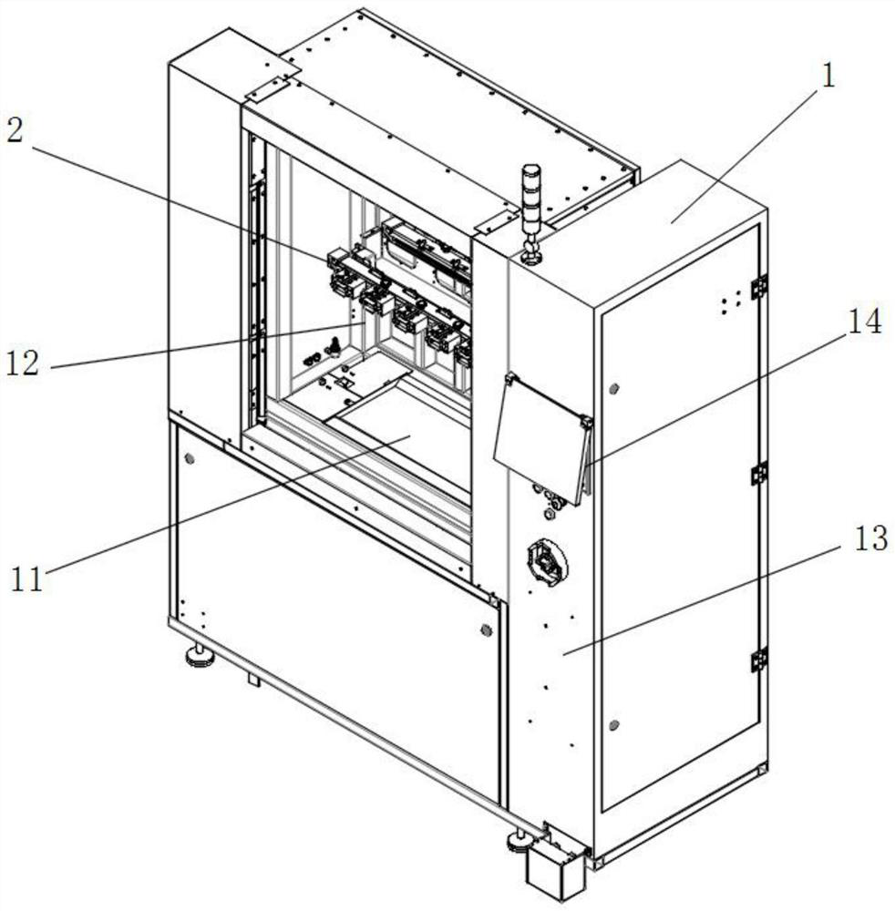
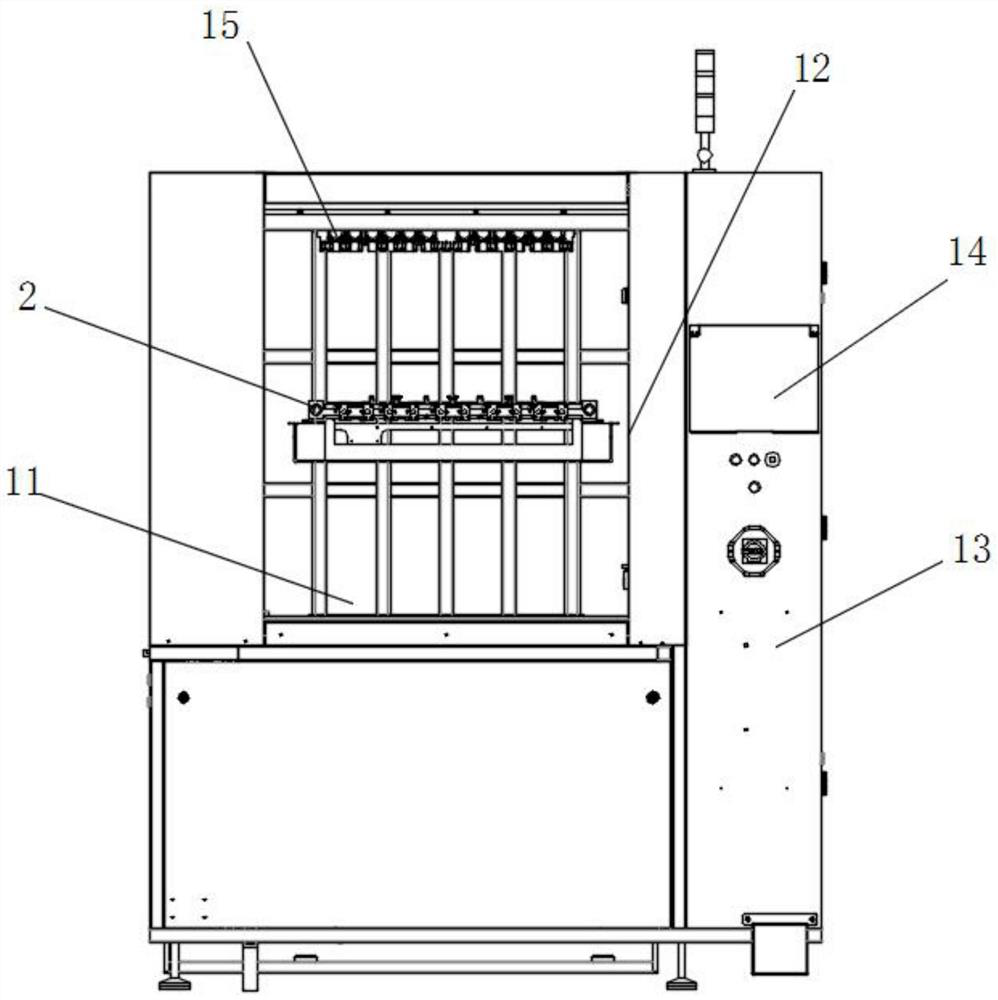
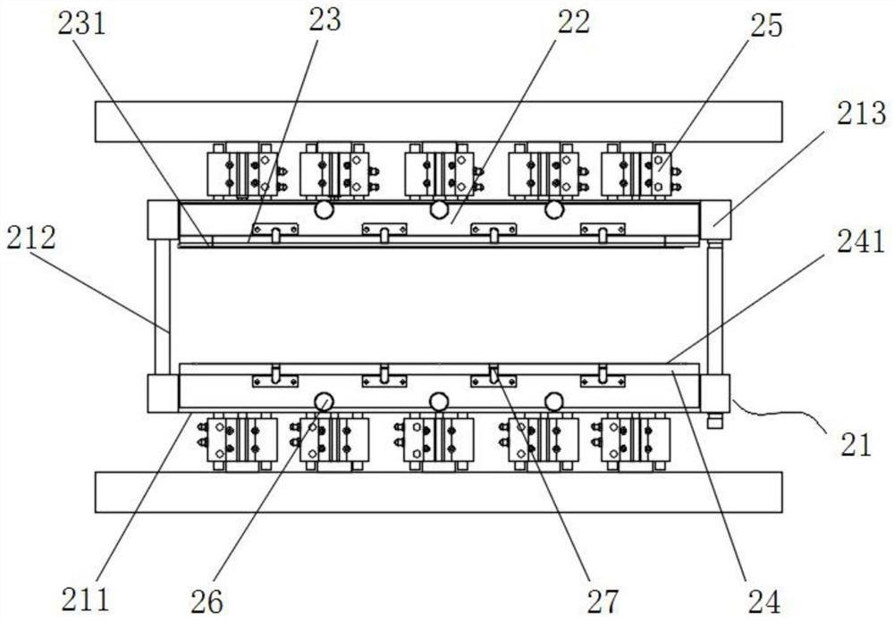
[0028] The present invention provides such as Figure 1-6 A clean vacuum resin plugging machine shown includes a body 1, the inside of which is provided with a vacuum chamber body 11, the vacuum chamber body 11 is provided with a sealed chamber door, and the top of the vacuum chamber body 11 A splint seat 15 is fixedly installed, and the inside of the vacuum chamber body 11 is provided with a plug module 2 that can lift and slide. The plug module 2 includes a module frame 21 and two sets of plug bases 22. The plug bases 22 are respectively detachably mounted on both sides of the module frame 21, and the two groups of plug bases 22 are driven to slide in opposite directions by translational drive equipment, and the two groups of plug bases 22 are respectively fixedly installed with a front plug head 23 and a rear plug head 24, a single-strand seal 231 is installed on the outside of the front plug head 23, a double-strand seal 241 is installed on the outside of the rear plug hea...

Embodiment 2

[0034] Such as Figure 3-5 A clean vacuum resin plugging machine shown includes a body 1, the inside of which is provided with a vacuum chamber body 11, the vacuum chamber body 11 is provided with a sealed chamber door, and the top of the vacuum chamber body 11 A splint seat 15 is fixedly installed, and the inside of the vacuum chamber body 11 is provided with a plug module 2 that can lift and slide. The plug module 2 includes a module frame 21 and two sets of plug bases 22. The plug bases 22 are respectively detachably mounted on both sides of the module frame 21, and the two groups of plug bases 22 are driven to slide in opposite directions by translational drive equipment, and the two groups of plug bases 22 are respectively fixedly installed with a front plug head 23 and a rear plug head 24, a single-strand seal 231 is installed on the outside of the front plug head 23, a double-strand seal 241 is installed on the outside of the rear plug head 24, and the The inside of th...


PUM


Abstract

The invention discloses a cleaning type vacuum resin hole plugging machine, and relates to the technical field of PCB hole plugging, the cleaning type vacuum resin hole plugging machine comprises a machine body, the machine body is internally provided with a vacuum bin body, the vacuum bin body is provided with a sealing bin door, the top of the vacuum bin body is fixedly provided with a clamping plate seat, and the vacuum bin body is internally provided with a plug head module capable of sliding in a lifting mode; the plug module comprises a module frame and two plug bases, the two plug bases are detachably installed on the two sides of the module frame respectively, and the two plug bases are driven by translation driving equipment to slide in the opposite directions. According to the invention, the hole plugging process is set from top to bottom, and the single-strand sealing strip is on the oil emitting surface of the board and is lower than the single-strand sealing strip, so that the oil emitting hole positions on the surface of the PCB cannot be stricken off during hole plugging of the whole board, the surface of the oil emitting board cannot be polluted, hole plugging of the whole board can be realized, selective hole plugging can also be realized, and meanwhile, the manufacturing time and the manufacturing cost of the jig are reduced.

Description

technical field [0001] The invention relates to the technical field of PCB board plugging holes, in particular to a clean vacuum resin plugging machine. Background technique [0002] PCB, the Chinese name is printed circuit board, also known as printed circuit board, is an important electronic component, a support for electronic components, and a carrier for electrical connections of electronic components. Because it is made using electronic printing, it is called a "printed" circuit board. [0003] The traditional production of PCB boards needs to be plugged with the help of a screen printing machine. The specific operation can be roughly divided into two steps. First, the screen fixed on the screen printing machine is aligned with the PCB board, and then the screen printing machine passes the screen. Make a plug hole. Most of the existing stencils adopt the structure of "aluminum sheet + mesh". The traditional whole board plug hole has the risk of contamination of the oi...

Claims


Application Information

Patent Timeline
IPC IPC(8): H05K3/00H05K3/40
CPCH05K3/0094H05K3/0008H05K3/40
Inventor 黄俊祥
Owner 深圳市深逸通电子有限公司
Why Eureka
Try Eureka