
Railway electronic speed limit indication board and application method

A speed limit sign, speed limit sign technology, applied in railway traffic management, railway car body parts, railway signal and safety, etc., can solve the problem of all operations being arranged in the "skylight point"

Pending Publication Date: 2022-05-10
LANZHOU JIAOTONG UNIV
View PDF0 Cites 0 Cited by
  • Summary
  • Abstract
  • Description
  • Claims
  • Application Information

AI Technical Summary

Problems solved by technology

[0004] Although the existing high-speed railways use ground transponders to transmit basic line information to locomotives, which can fundamentally realize intelligent control of trains, ordinary speed lines still need to artificially set temporary speed limit signs in view of investment restrictions and operational characteristics.
In addition, although there are "skylight points" for railway workers to work on the track, it is impossible to arrange all operations in the "skylight points". Therefore, it is necessary to develop a speed limit information for locomotives and provide A kind of railway electronic speed limit sign with accurate traffic information forecast

Method used


Image

  • Railway electronic speed limit indication board and application method
  • Railway electronic speed limit indication board and application method

Examples


Embodiment

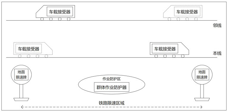
[0055] Such as Figure 1-2 As shown, this embodiment provides a railway electronic speed limit sign, including:

[0056] The ground speed limit board is set in the railway speed limit area to display speed limit information. The ground speed limit board includes an LED display connected to the main controller. 》(TG / 01A-2017) standard appearance, with bright LED dot matrix to display the speed limit, and can also be set by the user to light up only at night, using PLC as the main controller, which can adapt to the harsh outdoor environment. The ground speed limit board is equipped with a signal transmitter connected to the main controller in communication. The main controller controls the signal transmitter in the ground speed limit board located at the starting point of the speed limit of the railway speed limit area to transmit the speed limit command. The main controller Control the signal transmitter in the ground speed limit board at the speed limit end point of the railw...


PUM


Abstract

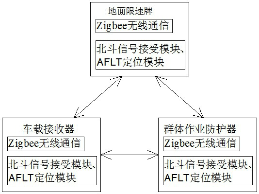
The invention discloses a railway electronic speed limit indicator and an application method, and the railway electronic speed limit indicator comprises a ground speed limit board which is arranged in a railway speed limit area and is used for displaying speed limit information; the vehicle-mounted receiver is arranged on the locomotive and is in two-way wireless communication connection with the ground speed limit board; and the group operation protector is arranged in a railway staff operation area and is in two-way wireless communication connection with the ground speed limit board and the vehicle-mounted receiver respectively. The ZigBee wireless communication technology is used for enabling every two of the ground speed limit board, the vehicle-mounted receiver and the group operation protector to be in two-way wireless communication connection, and mutual information transmission is facilitated. In addition, a Beidou signal receiving module and an AFLT positioning module are embedded in the ground speed limit board, the vehicle-mounted receiver and the group operation protector respectively, so that the position information of the ground speed limit board, the vehicle-mounted receiver and the group operation protector can be accurately acquired. According to the invention, not only is the driving instruction transmitted to the locomotive on the railway realized, but also the accurate coming train information forecast can be provided for the railway field operation personnel.

Description

technical field [0001] The invention relates to the technical field of railway safety protection, in particular to a railway electronic speed limit sign and an application method. Background technique [0002] The speed limit sign is an important signal sign of the railway. When the train speeds up at the speed limit point, the consequences will be unimaginable. In addition, when railway employees work on the road, they must also set up speed limit signs. This speed limit is not only on the main line, but also involves the speed limit of the adjacent lines. If the protection fails, it will cause irreparable and heavy losses, and the impact will be extremely bad. [0003] At present, the commonly used iron speed limit board lacks joint control with trains, so an electronic speed limit board with joint control function with trains developed by computer technology and modern communication technology is proposed to realize speed limit display and realize vehicle-ground Inter-c...

Claims


Application Information

Patent Timeline
IPC IPC(8): B61L23/00B61L23/06B61L27/40B61L27/70
CPCB61L23/00B61L23/06
Inventor 满世浩石广田刘滔满世甲马路顺马文杰徐上壹王宝玺满开泉
Owner LANZHOU JIAOTONG UNIV
Learn More