
Rural sewage aeration treatment device

A technology for treatment device and rural sewage, which is applied in biological water/sewage treatment, water/sludge/sewage treatment, special treatment targets, etc. Manual cleaning is easy and the effect of improving the contact area

Active Publication Date: 2022-05-10
深圳市粤昆仑环保实业有限公司
View PDF7 Cites 0 Cited by
  • Summary
  • Abstract
  • Description
  • Claims
  • Application Information

AI Technical Summary

Problems solved by technology

[0004] However, when the aeration tank treats the sewage, some dirt in the sewage is easy to precipitate and adsorb on the bottom inner wall of the aeration tank, and these dirt are easy to be cleaned if they are not cleaned for a long time. Deterioration and odor are usually cleaned regularly by manual cleaning tools. The cleaning cycle is short and labor-intensive

Method used


Image

  • Rural sewage aeration treatment device
  • Rural sewage aeration treatment device
  • Rural sewage aeration treatment device

Examples


Embodiment 1

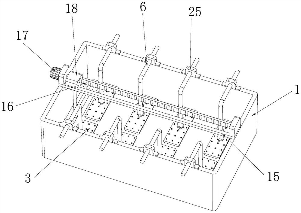
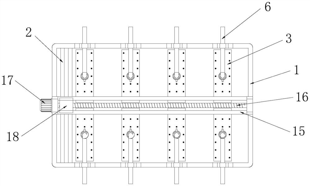
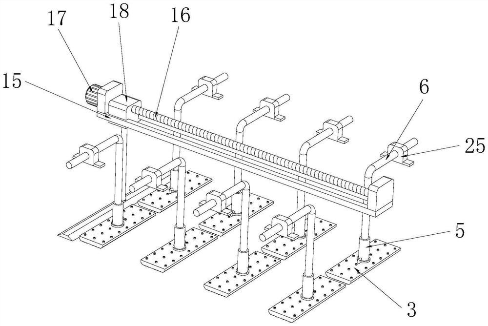
[0031] see Figure 1~5 , in an embodiment of the present invention, an aeration treatment device for rural sewage, comprising an aeration tank 1, a shovel plate 2 is provided at the bottom of the inner cavity of the aeration tank 1, and the bottom wall of the shovel plate 2 is in contact with the The inner wall of the bottom of the aeration tank 1 is in contact with each other. The aeration tank 1 is provided with a driving mechanism for driving the shovel plate 2 to move relative to the aeration tank 1. The aeration tank 1 is fixedly equipped with an air inlet pipe 6. The bottom end of the air inlet pipe 6 is provided with a connecting cylinder 5, the connecting cylinder 5 is slidingly fitted with the air inlet pipe 6, and the air inlet pipe 6 is elastically connected with the connecting cylinder 5, and the bottom end of the connecting cylinder 5 is fixed An aeration plate 3 is installed, and the aeration plate 3 communicates with the air inlet pipe 6 through the connecting c...

Embodiment 2

[0036] see Figure 4-8 , in the embodiment of the present invention, a piston 8 is fixedly installed at the bottom end of the intake pipe 6, and the piston 8 is slidingly fitted with the connecting cylinder 5, and the inner cavity of the connecting cylinder 5 is provided with a connecting pipe 9. The top end of the connecting pipe 9 is fixedly connected to the bottom wall of the piston 8, the bottom end of the connecting pipe 9 is fixedly connected to the top wall of the aeration plate 3, and a through hole is opened on the piston 8, and the connecting The top of the pipe 9 communicates with the inlet pipe 6 through a through hole, and the bottom end of the connecting pipe 9 communicates with the inner cavity of the aeration head 4; a spring 10 is arranged in the connecting cylinder 5, and the The top end of the spring 10 is fixedly connected to the bottom wall of the piston 8, the bottom end of the spring 10 is fixedly connected to the top wall of the aeration plate 3, the sp...

Embodiment 3

[0039] see Figure 9 and Figure 10 , in the embodiment of the present invention, one side of the bottom end of the aeration tank 1 is fixedly equipped with an impurity tank 20, and the top of the impurity tank 20 is provided with an opening, and the top wall of the impurity tank 20 is in contact with the aeration tank 1 The inner wall of the bottom is flush; the top of the impurity tank 20 is slidably installed with a cover 21, which is elastically connected to the inner wall of the aeration tank 1, and the top of the cover 21 is fixedly installed with a connection Rod 23, the connecting rod 23 is arranged in an L shape, and the end of the connecting rod 23 away from the cover 21 is fixedly equipped with a push plate 24, and the push plate 24 is arranged on the top side of the cover 21 close to the motor 17, When the push rod 19 moves toward the impurity tank 20, the push rod 19 pushes the push plate 24 to move to the right, thereby pushing the cover 21 to move to the right ...


PUM


Abstract

The invention relates to the technical field of sewage treatment, and discloses a rural sewage aeration treatment device which comprises an aeration tank, a shovel plate is arranged at the bottom of an inner cavity of the aeration tank, the bottom wall of the shovel plate is in contact with the inner wall of the bottom of the aeration tank, and a driving mechanism used for driving the shovel plate to move relative to the aeration tank is arranged on the aeration tank; the shoveling plate is driven by the driving mechanism to move relative to the inner wall of the bottom of the aeration tank, dirt on the inner wall of the bottom of the aeration tank is shoveled, and when the shoveling plate moves to be in contact with the aeration plate, the aeration plate is gradually pushed upwards, so that the shoveling plate can pass through the lower part of the aeration plate, and the aeration effect is improved. The aeration plate is always located at the bottom of the inner cavity of the aeration tank during aeration, so that the contact area of gas and sewage is increased, and the aeration plate moves upwards during cleaning, so that the aeration plate is prevented from hindering the movement of the shovel plate, the bottom wall of the aeration tank can be conveniently cleaned, dirt in the sewage is prevented from being attached to the bottom wall of the aeration tank, and the cleaning efficiency is improved. And subsequent manual cleaning is easier.

Description

technical field [0001] The invention relates to the technical field of sewage treatment, in particular to an aeration treatment device for rural sewage. Background technique [0002] The aeration tank is a biochemical reactor designed according to the characteristics of microorganisms. The degree of degradation of organic pollutants mainly depends on the aeration reaction conditions designed by people. The aeration tank uses activated sludge method for sewage treatment, and a certain amount of sewage is provided in the tank. The residence time satisfies the oxygen required by aerobic microorganisms and the mixing conditions for full contact between sewage and activated sludge. The aeration tank is mainly composed of three parts: the tank body, the aeration system and the water inlet and outlet. The pool body is generally made of reinforced concrete, and its planar shape is rectangular, square and circular. [0003] Chinese invention patent CN109721173A discloses an aeratio...

Claims


Application Information

Patent Timeline
Patent Type & Authority Applications(China)
IPC IPC(8): C02F3/12C02F101/30
CPCC02F3/12C02F2101/30C02F2303/14Y02W10/10
Inventor 周亮夏观强谭珞萍
Owner 深圳市粤昆仑环保实业有限公司
Learn More