Eureka AIR delivers breakthrough ideas for toughest innovation challenges, trusted by R&D personnel around the world.

Roadbed reinforcing structure for highway construction and construction technology of roadbed reinforcing structure

A technology for strengthening structures and subgrades, which is applied to road construction reinforcements, roads, roads, etc., can solve the problems of affecting the safety of groundwater source water quality, single use of reinforcement structures, failure to detect and give feedback in time, and achieve water quality protection. Improve driving comfort and reduce construction difficulty

Pending Publication Date: 2022-05-10
李晶
View PDF10 Cites 0 Cited by
  • Summary
  • Abstract
  • Description
  • Claims
  • Application Information

AI Technical Summary

Problems solved by technology

It is used for the reinforcement structure on the expressway roadbed. Through the cooperation between the fixed steel bar, the plane buried slab and the steel bar column, the original soil layer is stretched and fixed horizontally, so as to prevent the subsidence of the base layer caused by rainwater erosion, resulting in the expressway When the pavement is broken, under the action of horizontal H-shaped steel, vertical H-shaped steel and short H-shaped steel, the horizontal H-shaped steel, vertical H-shaped steel and short H-shaped steel are combined to form a horizontal reinforcement grid frame, so that the structure of the expressway subgrade is more stable. "Stable", the reinforcement structure uses H-shaped steel to strengthen the reinforcement, but when geological movement occurs underground and the underground soil uplift occurs, the reinforcement structure fails to detect and feedback in time, making the reinforcement structure Usability is relatively simple;
[0006] 3. The patent

Method used


Image

  • Roadbed reinforcing structure for highway construction and construction technology of roadbed reinforcing structure
  • Roadbed reinforcing structure for highway construction and construction technology of roadbed reinforcing structure
  • Roadbed reinforcing structure for highway construction and construction technology of roadbed reinforcing structure

Examples


Embodiment 1

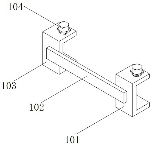
[0045] see figure 1 , figure 2 , Figure 5 with Image 6 , an embodiment provided by the present invention: a roadbed reinforcement structure for road construction, including a connection module 1 and a reinforcement module 5, and the connection module 1 is installed on the front and back of the reinforcement module 5;

[0046] Reinforcing module 5 comprises steel plate 501, steel bar fence 502, arc support plate 503, compression spring 504 and steel bar filter screen 505, and the inner wall of steel bar fence 502 is equipped with the steel bar frame that vertically and horizontally arranges, and the bottom wall of steel bar fence 502 is equipped with steel bar filter screen. Net 505, the top of the reinforced fence 502 is equipped with equidistantly arranged arc-shaped support plates 503, and the inner top wall of the arc-shaped support plates 503 is equipped with parallel arranged compression springs 504, and the bottom of the compression springs 504 is connected to the t...

Embodiment 2

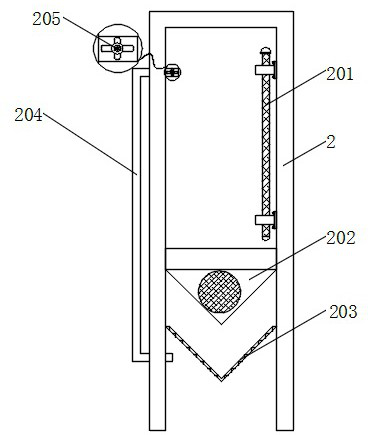
[0053] see figure 1 with image 3 , an embodiment provided by the present invention: a roadbed reinforcement structure for road construction, including a connection module 1 and an early warning prompt box 2, the front and back of the reinforcement module 5 are equipped with an early warning prompt box 2, and the early warning prompt box 2 is far away from the reinforcement A return pipe 204 is installed through the inner wall of one side of the module 5, and the tail end and the head end of the return pipe 204 are all located inside the early warning prompt box 2. The surface of the return pipe 204 is equipped with an electronic valve 205, and the inner wall of the early warning prompt box There is a liquid level sensor 201, and the liquid level sensor 201 is electrically connected to the electronic valve 205. The inner wall of the early warning prompt box 2 is equipped with a one-way valve 202 and an intercepting screen 203, and the one-way valve 202 is located at the liquid...

Embodiment 3

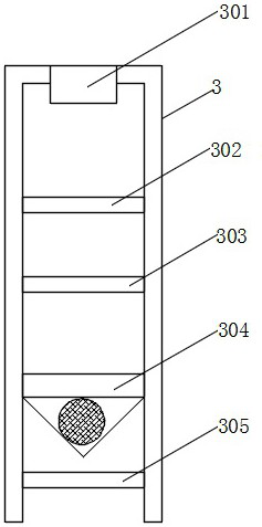
[0059] see figure 1 with Figure 4 , an embodiment provided by the present invention: a roadbed reinforcement structure for road construction, comprising a connection module 1 and an anti-filter tank 3, an anti-filter tank 3 is installed in the middle of two groups of reinforcement modules 5, and an anti-filter tank 3 is installed on the top of the anti-filter tank 3 Water inlet 301 is arranged, fine sand layer 302 and charcoal layer 303 are installed on the inwall of anti-filter tank 3, and charcoal layer 303 is positioned at the below of fine sand layer 302, No. two one-way valve 304 and stopper are installed on the inwall of anti-filter tank 3 Net 305, retaining net 305 is positioned at the bottom of No. 2 one-way valve 304, and No. 2 check valve 304 is positioned at the bottom of charcoal layer 303, and the bottom of anti-filtration tank 3 is open design.

[0060] Specifically, during use, the rainwater on the road surface contains pollutants. In order to reduce the pollu...


PUM


Abstract

The roadbed reinforcing structure for highway construction comprises connecting modules and a reinforcing module, and the connecting modules are installed on the front face and the back face of the reinforcing module; the reinforcing module comprises a steel plate, a steel bar fence, arc-shaped supporting plates, compression springs and a steel bar filter screen, the steel bar filter screen is installed on the bottom wall of the steel bar fence, the arc-shaped supporting plates which are arranged at equal intervals are installed on the top of the steel bar fence, and the compression springs which are arranged in parallel are installed on the inner top walls of the arc-shaped supporting plates; the bottom of the compression spring is connected with the top of the steel bar frame, and a steel plate is installed on the top of the arc-shaped supporting plate. And early warning prompt boxes are installed on the front faces and the back faces of the reinforcing modules correspondingly, a reverse filter tank is installed between the two reinforcing modules, and a settlement compensation box is installed in a steel bar filter screen in a penetrating mode. By arranging the reinforcing module, roadbed reinforcing treatment of an asphalt pavement and a cement pavement can be achieved, and the applicability of the reinforcing structure is enhanced.

Description

technical field [0001] The invention relates to the technical field of roadbed reinforcement, in particular to a roadbed reinforcement structure for road construction and a construction process thereof. Background technique [0002] There are mostly two types of highway pavement in our country, one is cement pavement and the other is asphalt pavement. The advantages and disadvantages of the two pavements are different, and they are complementary to a large extent. For the construction of various road surfaces, the road subgrade needs to be reinforced before construction to ensure the normal use of the road surface and subgrade, thereby ensuring the quality of the construction road under various geology, especially soft and collapsed geology, and ensuring the effective service life of the road. [0003] The defect that existing roadbed reinforcement equipment exists is: [0004] 1. The patent document CN111778800A discloses a highway subgrade reinforcement structure and meth...

Claims


Application Information

Patent Timeline
IPC IPC(8): E01C3/04E01C11/00E01C11/16E01C11/22B01D36/02B01D35/16G08B21/24F16F15/067
CPCE01C3/04E01C11/00E01C11/165E01C11/225B01D36/02B01D35/16G08B21/24F16F15/067
Inventor 王雅敏李晶杨海刚李岩李鑫蕾
Owner 李晶
Why Eureka
Eureka Blog
Learn More