High-pressure packing sealing structure
A stuffing sealing and high pressure technology, which is applied in engine sealing, heat exchanger sealing device, lighting and heating equipment, etc. It can solve the problems that the inner tube of non-metallic heat exchanger cannot withstand high pressure, cannot be welded and sealed, and the strength is difficult to balance.
- Summary
- Abstract
- Description
- Claims
- Application Information
AI Technical Summary
Problems solved by technology
Method used
Image


Examples
Embodiment 1
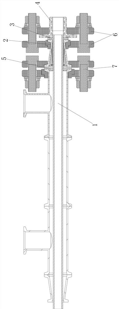
[0021] according to Figure 1-3 As shown, a high-pressure packing seal structure includes a metal or non-metallic inner tube 1, an outer tube (shell) and a packing seal structure connecting the inner tube 1 to the outer tube (shell), a conventional cylindrical packing seal, It is difficult to balance the strength of the inward hugging, which will easily lead to the rupture of the inner tube 1, and the non-metallic inner tube 1 and the metal outer tube cannot be welded, so that the existing non-metallic sleeve heat exchanger, such as silicon carbide Microchannel reactors, graphite heat exchangers, etc., cannot withstand high pressure.
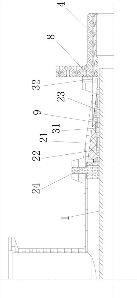
[0022] In the present invention, the packing sealing structure includes a T-shaped sealing pressure ring sleeve 3 set on the inner tube 1, a wedge-shaped inclined packing structure 2, a flange flange joint 4 and the wedge-shaped inclined packing structure 2. A limited and fixed inner compression stopper 5. The T-shaped sealing compression ring ...
Embodiment 2
[0025] The difference from Example 1 is that the wedge-shaped inclined-plane packing structure 2 includes a conical packing cavity 21, a conical packing compression ring sleeve 22 and a diamond-shaped packing compression ring sleeve 23, and the diamond-shaped packing compression ring sleeve 23, conical packing The packing compression ring sleeve 22 and the conical packing cavity 21 are sequentially set on the sleeve part 31 of the T-shaped sealing compression ring sleeve 3, and pass through the conical packing under the limit of the inner compression stopper 5 The cooperation of the cavity 21, the tapered packing ring sleeve 22 and the rhombic packing ring sleeve 23 converts the axial thrust into an inwardly embracing radial sealing force, so that the wedge-shaped inclined packing structure 2 is pressed and connected to the On the casing portion 31 of the T-shaped sealing compression ring sleeve 3 , the T-shaped sealing compression ring sleeve 3 is attached to the outer wall of...
Embodiment 3
[0033] The difference from Example 2 is that: the wedge-shaped inclined packing structure 2 also includes an automatic compensation spring device 24, and the automatic compensation spring device 24 is sleeved on the inner tube 1, and generally can be sleeved on the inner tube 1, one end of the self-compensating spring device 24 resists on the inner compression block 5, and the other end resists on the wide surface of the tapered packing pressure ring sleeve 22, and continuously supports the tapered The stuffing ring sleeve 22 produces axial thrust.
[0034] Specifically, the self-compensating spring device 24 provides a continuous axial thrust, and the tapered packing pressure ring sleeve 22 in the wedge-shaped inclined packing structure 2 amplifies the thrust and converts it into a circumferential seal evenly tightened inward. pressure.
[0035] The compressed length and strength of the spring of the automatic compensation spring device 24 can be adjusted according to the ac...
PUM
 Abstract
Description
Claims
Application Information