
Galvanometer calibration system and method

A calibration system and calibration method technology, applied in the field of galvanometer calibration system, can solve the problems of low efficiency, low precision, complicated galvanometer calibration, etc.

Pending Publication Date: 2022-05-10
SEIZET TECH SHEN ZHEN CO LTD
View PDF6 Cites 0 Cited by
  • Summary
  • Abstract
  • Description
  • Claims
  • Application Information

AI Technical Summary

Problems solved by technology

[0008] The main purpose of the present invention is to provide a vibrating mirror calibration system and method, aiming to solve the technical problems of complicated vibrating mirror calibration, low precision and low efficiency in the prior art

Method used


Image

  • Galvanometer calibration system and method
  • Galvanometer calibration system and method
  • Galvanometer calibration system and method

Examples


Embodiment Construction

[0069] It should be understood that the specific embodiments described here are only used to explain the present invention, not to limit the present invention.

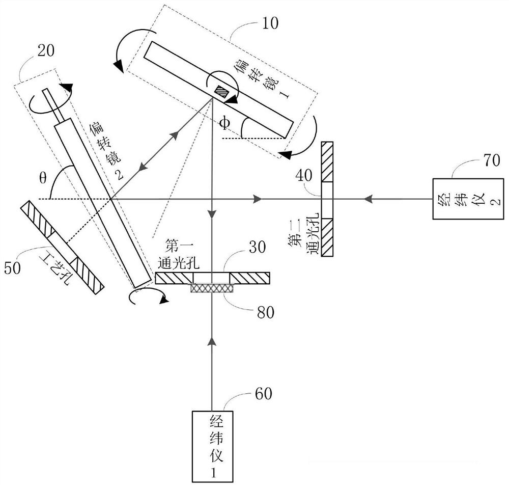
[0070] refer to figure 1 , figure 1 It is a schematic structural diagram of an embodiment of the galvanometer calibration system of the present invention, and an embodiment of the galvanometer calibration system of the present invention is proposed.

[0071] The vibrating mirror calibration system includes: a first vibrating mirror structure (10), a second vibrating mirror structure (20), a first light passing hole (30), a second light passing hole (40), a process hole (50), Theodolite 1 (60), theodolite 2 (70), optical flat crystal (80);

[0072] The first light hole (30) and the second light hole (40) are respectively used as the light entrance and the light exit of the theodolite 1 (60) and the theodolite 2 (70);

[0073] The optical flat crystal (80) is close to the first vibrating mirror structure (10), the se...


PUM


Abstract

The invention relates to the technical field of optical confocal, and discloses a galvanometer calibration system and method.The system comprises a first galvanometer structure, a second galvanometer structure, a first light through hole, a second light through hole, a process hole, a theodolite 1, a theodolite 2 and an optical flat, and the first light through hole and the second light through hole serve as a light inlet and a light outlet of the theodolite 1 and a light outlet of the theodolite 2 respectively; the optical flat is tightly attached to the first galvanometer structure, the second galvanometer structure or the process hole, the optical flat is used for reflecting laser beams emitted by the theodolite 1 and the theodolite 2 to an emitting point so as to calibrate the theodolite 1 and the theodolite 2, and the theodolite 1 and the theodolite 2 are used for calibrating the first galvanometer structure and the second galvanometer structure. The method adopts the theodolite to calibrate the galvanometer, is simple in system structure, is combined with devices such as optical flat, and is high in calibration precision and high in efficiency.

Description

technical field [0001] The invention relates to the technical field of optical confocal, in particular to a vibrating mirror calibration system and method. Background technique [0002] The optical system of the existing galvanometer is a spatial layout. The assembly scheme of the deflection mirror is that the laser light source reaches the top, and a standard center ring is placed horizontally. By adjusting the attitude of the deflection mirror, the laser beam is reflected to the cross center of the center ring after passing through the deflection mirror. This technology requires professional fixtures for spatial layout for calibration and measurement, and is not suitable for transplantation in the civilian market. At the same time, the accuracy is not high, and the operation is more dangerous. The disadvantages are as follows: [0003] a. The optical system is a spatial layout. The optical system is spatially distributed during the transmission process. In the use of rob...

Claims


Application Information

Patent Timeline
Patent Type & Authority Applications(China)
IPC IPC(8): G01H17/00G01M13/00
CPCG01H17/00G01M13/00Y02P10/25
Inventor 刘国强陈力强李晓康
Owner SEIZET TECH SHEN ZHEN CO LTD
Learn More