High-voltage switch cabinet body and internal fixed installation structure thereof

A technology of high-voltage switchgear and installation structure, which is applied to the cooling/ventilation of substation/switchgear, details of substation/switch layout, substation/power distribution device shell, etc., which can solve the problem of installation size limitation and switchgear without a stable and fixed installation structure , unable to install electrical components of various sizes and models, etc., to achieve the effect of high installation efficiency and convenient and quick use

Inactive Publication Date: 2022-05-10
盐城邦瑞电气有限公司
View PDF0 Cites 0 Cited by
  • Summary
  • Abstract
  • Description
  • Claims
  • Application Information

AI Technical Summary

Problems solved by technology

[0004] Therefore, the present invention provides a high-voltage switchgear cabinet body and its internal fixed installation structure, which is composed of a three-sided clamping mechanism composed of side panels, rear panels, pressure plates, and bases, as well as airbag seats and airbag cushions. The auxiliary clamping mechanism can quickly install and fix different types of electrical components to solve the problem that there is no stable fixed installation structure inside the traditional switchgear, or the installation size is relatively limited, and it is impossible to install various sizes of electrical components.

Method used


Image

  • High-voltage switch cabinet body and internal fixed installation structure thereof
  • High-voltage switch cabinet body and internal fixed installation structure thereof
  • High-voltage switch cabinet body and internal fixed installation structure thereof

Examples


Embodiment Construction

[0030] The implementation mode of the present invention is illustrated by specific specific examples below, and those who are familiar with this technology can easily understand other advantages and effects of the present invention from the contents disclosed in this description. Obviously, the described embodiments are a part of the present invention. , but not all examples. Based on the embodiments of the present invention, all other embodiments obtained by persons of ordinary skill in the art without making creative efforts belong to the protection scope of the present invention.

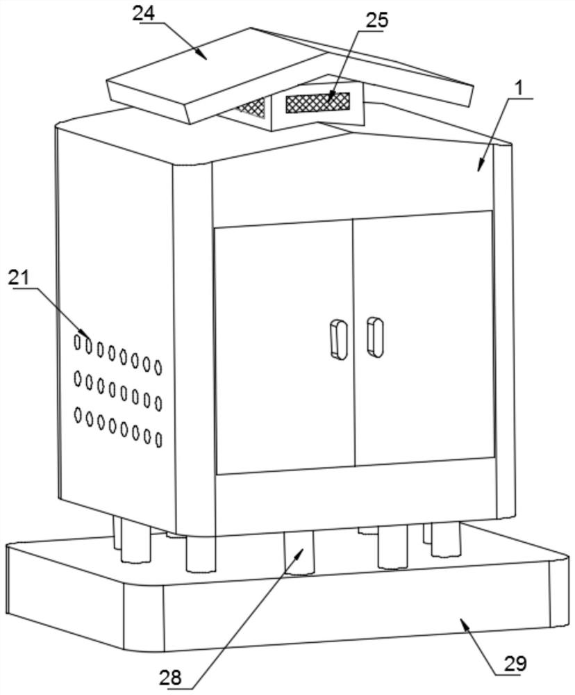
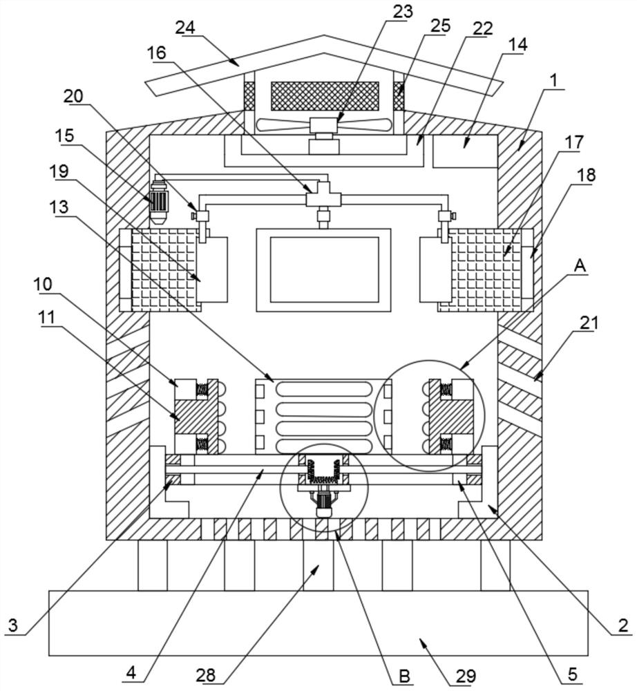
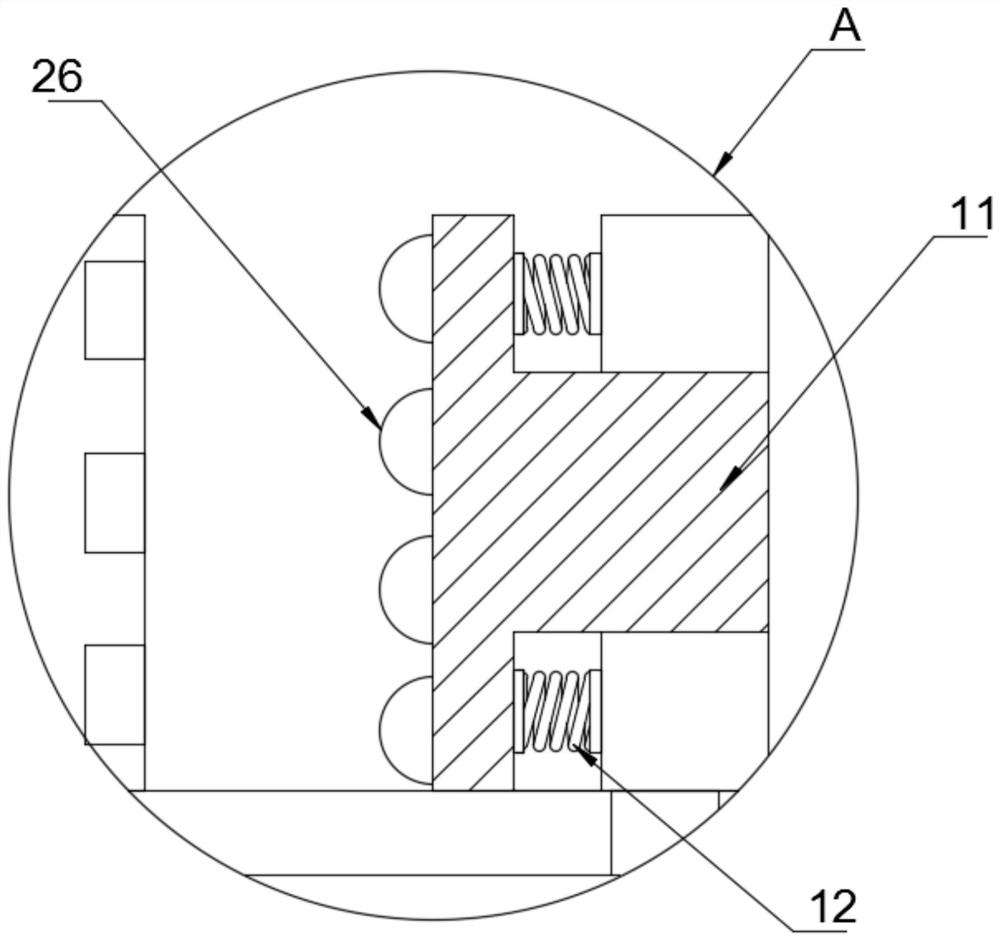
[0031] Refer to attached Figure 1-7 , the internal fixed installation structure of a high-voltage switchgear provided by the present invention includes a cabinet body 1, and the interior of the cabinet body 1 is provided with a three-side clamping mechanism and an auxiliary clamping mechanism;

[0032] The three-sided clamping mechanism includes two symmetrically distributed bottom plates 2, an...


PUM


Abstract

The invention discloses a high-voltage switch cabinet body and an internal fixed mounting structure thereof, and the technical scheme is that the high-voltage switch cabinet body comprises a cabinet body, and a three-side clamping mechanism and an auxiliary clamping mechanism are arranged in the cabinet body; the three-side clamping mechanism comprises two symmetrically-distributed bottom plates, a base is fixedly connected to the inner sides of the two bottom plates, two symmetrically-distributed sliding grooves and a cavity located between the two sliding grooves are formed in the base, and threaded rods and sliding blocks are embedded in the two cavities correspondingly. The high-voltage switch cabinet body and the internal fixed mounting structure thereof have the beneficial effects that by arranging a three-side clamping mechanism composed of the side plates, the rear plate, the pressing plate, the base and the like and an auxiliary clamping mechanism composed of the air bag seat, the air bag cushion and the like, electrical elements of different models can be quickly mounted and fixed; the problems that no stable fixed installation structure exists in a traditional switch cabinet, or the installation size is limited, and electrical elements of various sizes and models cannot be installed are solved.

Description

technical field [0001] The invention relates to the technical field of switch cabinets, in particular to a high-voltage switch cabinet body and its internal fixed installation structure. Background technique [0002] High-voltage switchgear refers to the role of on-off, control or protection in power system power generation, transmission, distribution, power conversion and consumption. The switchgear has functions such as overhead incoming and outgoing lines, cable incoming and outgoing lines, and bus connection. It is mainly applicable to various places such as power plants, substations, petrochemicals, metallurgical steel rolling, light industry textiles, factories and mines, residential quarters, high-rise buildings, etc. In actual use, it is often necessary to place and install electrical components such as branch lines inside the switch cabinet box, but there is no stable fixed installation structure inside the traditional switchgear, or the installation size is relativ...

Claims


Application Information

Patent Timeline
Patent Type & Authority Applications(China)
IPC IPC(8): H02B1/50H02B1/54H02B1/56H02B1/28H02B1/30H02B1/32
CPCH02B1/50H02B1/54H02B1/565H02B1/28H02B1/30H02B1/32
Inventor 单正左
Owner 盐城邦瑞电气有限公司
Why Eureka
Try Eureka