Three-phase common-box insulator assembly and GIS

A technology of three-phase common box and insulators, which is applied in the direction of electrical components, switchgear settings, switchgear, etc., can solve the problems of high design and processing costs, and achieve the effects of improving service life, suppressing partial discharge, and strong versatility

Pending Publication Date: 2022-05-10
HENAN PINGGAO ELECTRIC
View PDF10 Cites 0 Cited by
  • Summary
  • Abstract
  • Description
  • Claims
  • Application Information

AI Technical Summary

Problems solved by technology

[0007] The purpose of the present invention is to provide a three-phase common box insulator assembly to solve the technical problem in the prior art that two kinds of three-phase common box insulators need to be equipped to meet different operating conditions, resulting in high design and processing costs

Method used


Image

  • Three-phase common-box insulator assembly and GIS
  • Three-phase common-box insulator assembly and GIS
  • Three-phase common-box insulator assembly and GIS

Examples


Embodiment 1

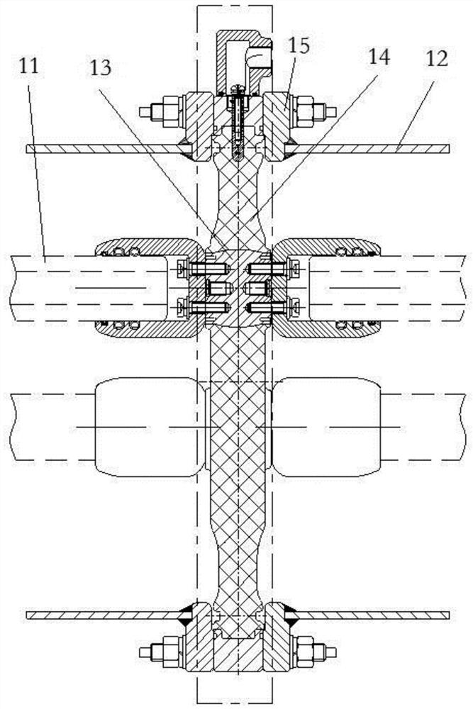
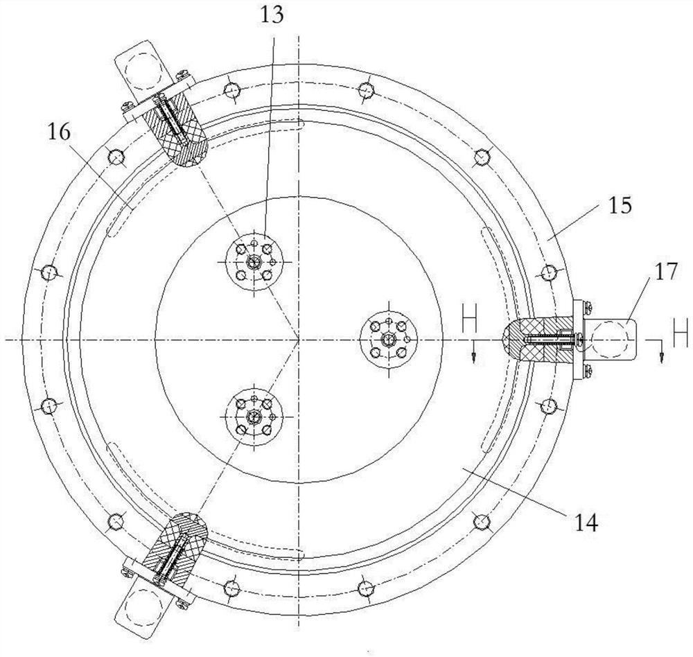
[0060] like figure 1 and figure 2 As shown, the GIS includes a shell 12 and a three-phase common box insulator assembly. A three-phase central conductor 11 is arranged inside the shell 12. The three-phase common box insulator assembly includes a three-phase common box insulator, and the three-phase common box insulator is a disc insulator. The three-phase common box insulator includes a three-phase central insert 13 arranged in the shape of "pin", a flange 15, and an insulating part 14 arranged between the central insert 13 and the flange 15. The three-phase central conductor 11 is connected to the three-phase The central inserts 13 are connected one by one, and the housing 12 is connected with the flange 15 . Corresponding to each central insert 13 in the insulating part 14 is cast with an electrode 16 , and the electrode 16 is arranged correspondingly to the corresponding central insert 13 along the radial direction.

[0061] In this example, if Figure 2 to Figure 4 As ...

Embodiment 2

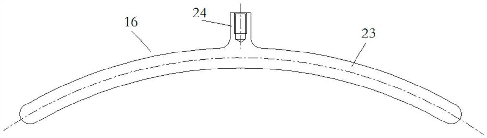
[0072] The difference between this embodiment and Embodiment 1 is that: in Embodiment 1, a threaded hole is provided on the connecting portion 24, and the charging display wiring body includes a connecting bolt 19 matched with the threaded hole, and the connecting bolt 19 is provided with a connection bolt 19 for connecting with the charging display device. Connected leads 22. In this embodiment, a light hole is provided on the connection part, and the charged display wiring body includes a polished rod, which passes through the radial through hole on the flange to cooperate with the light hole of the connection part, and the end of the polished rod far away from the central insert is provided with a Lead wires connected to live display devices. In other embodiments, the threaded hole on the connecting part is canceled, and when it is necessary to monitor the live display condition, the insulating seat is fixed on the outer peripheral surface of the flange, and a metal insert ...

Embodiment 3

[0074] The difference between this embodiment and Embodiment 1 is that in Embodiment 1, the joint 17 has a threading channel 18 for the lead wire 22 to pass through, and the threading channel 18 includes a threading entrance for the lead wire 22 to pass through and a threading exit for the lead wire 22 to pass through. , the threading entrance communicates with the radial through hole of the flange 15, and the threading channel 18 is an L-shaped channel. In this embodiment, the joint has a "one"-shaped threading channel, and the threading channel's threading entrance and threading exit are located on the same straight line. In other embodiments, the joints are omitted, and in order to prevent the wiring bolts from being exposed, insulating resin may be poured on the wiring bolts for protection.


PUM


Abstract

The invention relates to a three-phase common-box insulator assembly and a GIS. The three-phase common-box insulator assembly comprises three-phase center inserts arranged in a shape like a Chinese character'pin ', a flange and an insulating part arranged between the center inserts and the flange, electrodes are integrally poured in the insulating part and correspond to the center inserts, and the electrodes and the corresponding center inserts are correspondingly arranged in the radial direction. The electrode comprises an arc-shaped part which corresponds to the central insert and extends in the circumferential direction of the insulating part, and further comprises connecting parts, the connecting parts are located on the side, opposite to the central insert, of the arc-shaped part, and radial through holes corresponding to the connecting parts are formed in the flange; the connecting part is used for being connected with an electrification display wiring body penetrating into the radial through hole when the electrification condition is monitored, so that the electrode is communicated with the electrification display device; the connecting part is further used for being connected with a grounding piece penetrating into the radial through hole during grounding shielding, and the flange is provided with a grounding piece connecting part used for being connected with the grounding piece.

Description

technical field [0001] The invention relates to a three-phase common box insulator assembly and a GIS, in particular to an embedded electrode in the insulator. Background technique [0002] In the prior art, in order to accurately reflect and detect the electrification of the main circuit in the GIS, a electrification display device is often used for detection. The charged display device uses the electric field coupling between the high-voltage electric field and the sensor to conduct an inductive test outside a safe distance, output a locking signal, and implement mandatory locking of the operating mechanism to prevent misoperation and play a role in ensuring personal safety and equipment safety. Crucial role. [0003] At present, the electrification display probe used for GIS is usually installed on the cover to detect the electrification status of the product. Specifically, a pullout is opened on the cylinder of the GIS and the cover is installed. This design scheme has ...

Claims


Application Information

Patent Timeline
Patent Type & Authority Applications(China)
IPC IPC(8): H02B13/035H02B13/065H02B13/075H02B13/025
CPCH02B13/0358H02B13/065H02B13/0356H02B13/0352H02B13/075H02B13/025
Inventor 毕海波康留涛黄坤鹏李健李鹏李建彬赵平高博远郭良浩匡旭良吴运泽娄晓丹司昌杰刘奕杉张琳琳赵营李向远武亚军段启超李世亚李丹丹
Owner HENAN PINGGAO ELECTRIC
Why Eureka
Try Eureka