Molecular sieve production equipment
A production equipment and molecular sieve technology, applied in the field of separation, can solve the problems of unsatisfactory sorting effect, insufficient sorting, and inability to sort molecular sieves, etc., and achieve the effect of improving the sorting effect, facilitating maintenance and cleaning, and avoiding clogging.
- Summary
- Abstract
- Description
- Claims
- Application Information
AI Technical Summary
Problems solved by technology
Method used
Image

Examples
Embodiment 1
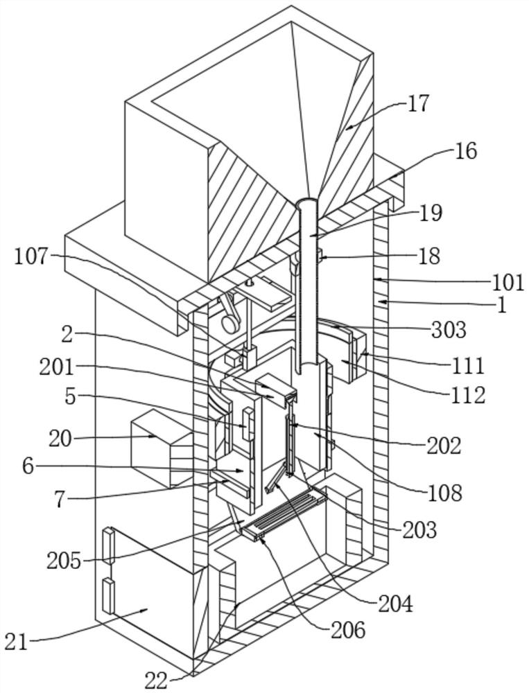
[0040] like figure 1 - Figure 11 As shown, the embodiment of the present invention provides a molecular sieve production equipment, including a vibration component 1, a stretching component 2 and a rotating component 3, the vibration component 1 is used to vibrate the molecular sieve and improve the sorting efficiency, and the stretching component 2 is used for In order to adjust the pore size of molecular sieve sorting and assist in improving the sorting specifications, the rotating component 3 is used to assist the molecular sieve rotation and improve the sorting effect, the vibration component 1 is used to drive the stretching component 2 to vibrate, and the rotating component 3 drives the The tension assembly 2 rotates, and the tension assembly 2 is installed inside the vibration assembly 1 .
Embodiment 2
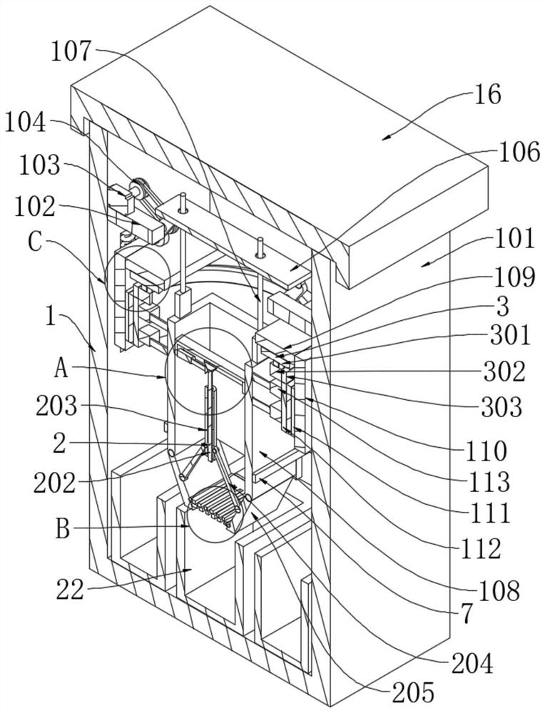
[0042] Based on the technical solution of the first embodiment, further: the vibration assembly 1 includes a cabinet 101 , a support plate 102 , a motor 103 , a belt drive pair 104 , a rotating plate 105 , a traction plate 106 , an electric push rod 1 107 , and a storage box 108 , hitting plate 109, lifting plate 110, first annular plate body 111, second annular plate body 112, telescopic rod 113 and roller 114;
[0043] One side of the support plate 102 is symmetrically installed on the inner side wall of the cabinet 101, the number of the support plate 102 is two, the upper surface of one support plate 102 is installed on the lower surface of the motor one 103, and one side of the rotating plate 105 is rotatably connected to the motor through a bearing. On the upper surfaces of the two support plates 102, the number of rotating plates 105 is two, the output shaft of the motor one 103 is installed on one side of the belt drive pair 104, and the other side of the belt drive pai...
Embodiment 3
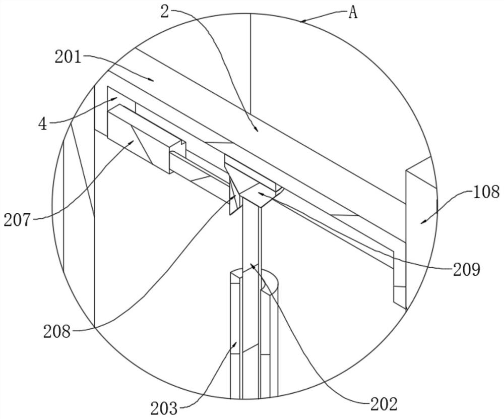
[0047] Based on the technical solution of the first embodiment, further: the stretching assembly 2 includes a fixed plate 201, a threaded rod 202, a threaded sleeve 203, a stretching plate 204, a rotating baffle 205, a sliding filter plate 206, a second motor 207, a first bevel gear 208 and second bevel gear 209;
[0048] The inner side wall of the storage box 108 is installed on the outer side wall of the fixing plate 201, the lower surface of the fixing plate 201 is provided with a groove 4, the inner side wall of the groove 4 is installed on one side of the second motor 207, and the output shaft of the second motor 207 is installed On one side of the first bevel gear 208, the upper surface of the second bevel gear 209 is rotatably connected to the inner top wall of the groove 4 through a bearing, and the other side of the first bevel gear 208 is engaged with the second bevel gear The outer side wall of 209, the lower surface of the second bevel gear 209 is welded to the top...
PUM
 Abstract
Description
Claims
Application Information
 - R&D
- Intellectual Property
- Life Sciences
- Materials
- Tech Scout
- Unparalleled Data Quality
- Higher Quality Content
- 60% Fewer Hallucinations
Browse by: Latest US Patents, China's latest patents, Technical Efficacy Thesaurus, Application Domain, Technology Topic, Popular Technical Reports.
© 2025 PatSnap. All rights reserved.Legal|Privacy policy|Modern Slavery Act Transparency Statement|Sitemap|About US| Contact US: help@patsnap.com