

Heat storage type flat flame burner
A flat-flame burner and regenerative technology, applied in the direction of burner, combustion method, combustion type, etc., can solve the problems of short service life of the burner, inability to adjust the thickness and diameter of the fire plate, and the drift of the flue gas
- Summary
- Abstract
- Description
- Claims
- Application Information
AI Technical Summary
Problems solved by technology
Method used
Image

Examples
Embodiment Construction
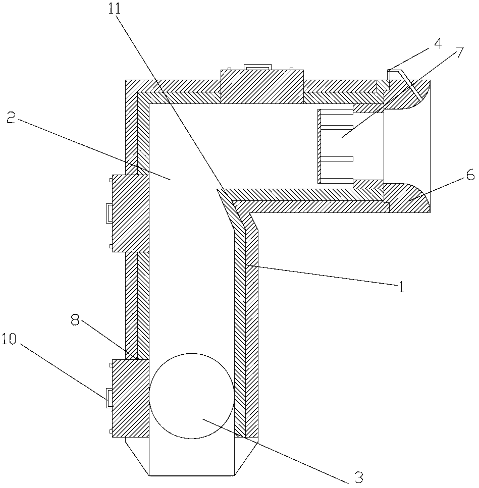
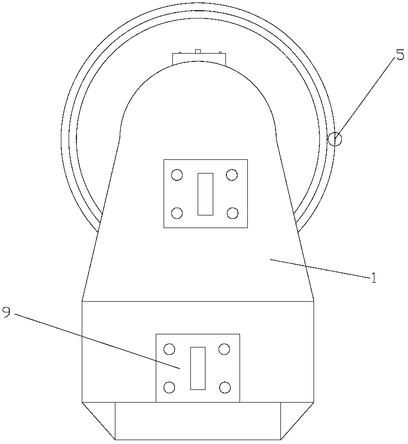
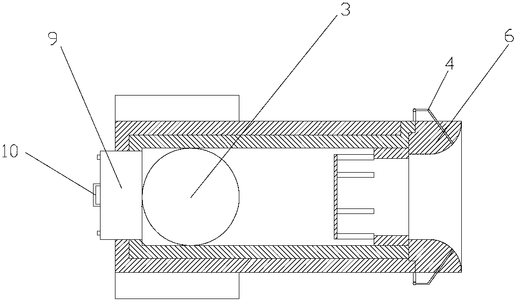
[0016] A regenerative flat flame burner of the present invention will be further described below in conjunction with the accompanying drawings. Such as figure 1 , figure 2 , image 3 As shown, a regenerative flat-flame burner includes an L-shaped burner body 1. A channel 2 for flue gas / air is provided in the burner body 1. The axis of the channel 2 coincides with the axis of the burner body 1. A regenerator 3 is provided in the passage 2, a fuel pipe 4 is provided on the burner body 1 and a bell-shaped burner brick 6 connected to the outlet end of the fuel pipe 4, and a swirler 7 is provided in the passage 2 , the swirler 7 is located in the outlet end of the channel 2, specifically the swirler 7 is located at the end of the smoke or air pipe 2 when the fire is sprayed, and the swirler 7 is detachably connected to the channel 2, so The inlet direction of the swirler 7 is perpendicular to the axial direction of the swirler 7 and is tangent to the inner wall of the swirler 7...
PUM
 Abstract
Description
Claims
Application Information