Heat conducting fiber, manufacture method thereof and illuminating device provided with same

A heat-conducting fiber and lighting device technology, which is applied in the direction of lighting devices, lighting device components, lighting device cooling/heating devices, etc., can solve the problems of heat dissipation system failure, affecting thermal conductivity, etc., and achieve good flexibility and high Reliability, easy-to-manufacture effects

Inactive Publication Date: 2013-08-14
OSRAM GMBH
View PDF0 Cites 0 Cited by
  • Summary
  • Abstract
  • Description
  • Claims
  • Application Information

AI Technical Summary

Problems solved by technology

However, in the production process, in order to install the heat pipe with high hardness in the integrated electronic device, it needs to be bent and stamped into a suitable shape, which will affect its thermal conductivity
Especially if the heat pipe is damaged or broken somewhere, it will lead to the failure of the entire cooling system

Method used


Image

  • Heat conducting fiber, manufacture method thereof and illuminating device provided with same
  • Heat conducting fiber, manufacture method thereof and illuminating device provided with same
  • Heat conducting fiber, manufacture method thereof and illuminating device provided with same

Examples


Embodiment Construction

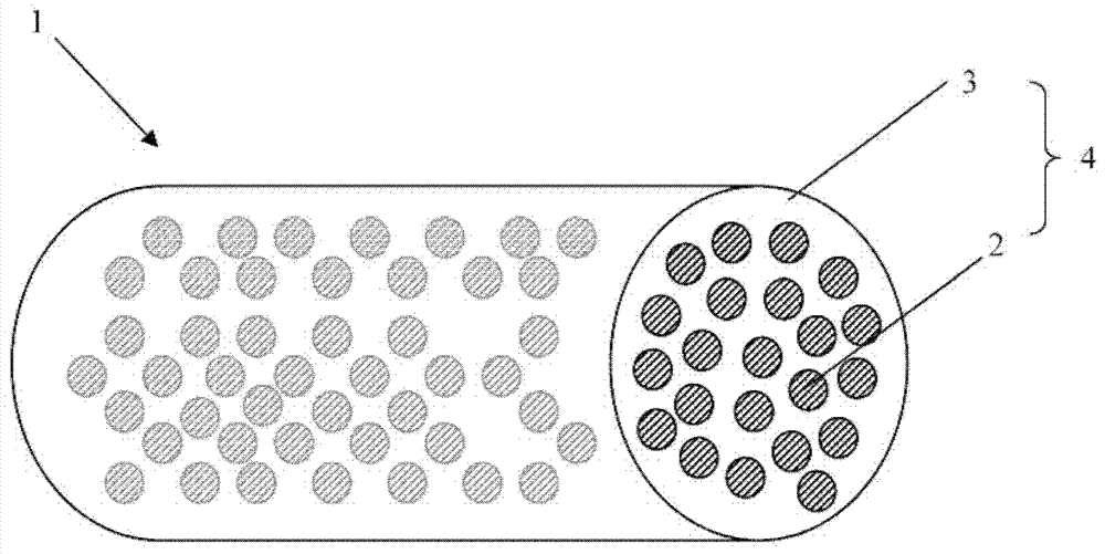
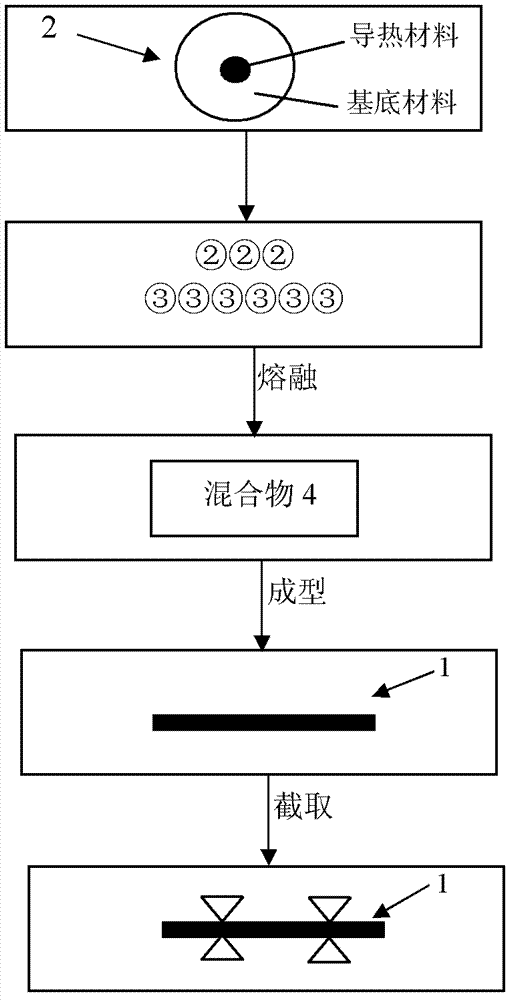
[0031] figure 1 A perspective view of a thermally conductive fiber according to a first embodiment of the present invention is shown. Elongated heat-conducting fibers 1 are schematically shown in the figure. In practice, the diameter of the thermally conductive fibers 1 may be less than 1 mm. After a large number of heat-conducting particles 2 and plastic particles 3 (shown directly as the matrix of the heat-conducting fiber 1 in the figure), for example, after melting, the mixture 4 of the heat-conducting particles 2 and the plastic particles 3 can be processed into a fibrous product through a molding process, The thermally conductive fibers 1 are formed after the cooling treatment. In order to achieve good heat conduction properties, the hard or flexible base material is especially doped with micron or nanoscale heat conduction materials, thereby forming heat conduction particles 2 . The thermally conductive material may account for 20%-50% of the thermally conductive par...


PUM

PropertyMeasurementUnit
diameteraaaaaaaaaa

Abstract

The invention relates to a heat conducting fiber (1). The heat conducting fiber (1) is characterized by comprising a mixture manufactured by heat conducting particles (2) and plastic particles (3), wherein the heat conducting particles (2) are made from a substrate material doped with a micron-scale or nano-scale heat conducting material. The heat conducting fiber is simple in manufacture and good in flexibility, and good heat conducting performance and high reliability can be achieved under the condition that multiple heat conducting fibers are integrated to form a heat conducting fiber beam for use. In addition, the invention further relates to a manufacture method of the heat conducting fiber and an illuminating device provided with the heat conducting fiber.

Description

technical field [0001] The invention relates to a heat-conducting fiber, a method for manufacturing the heat-conducting fiber and an illuminating device with the heat-conducting fiber. Background technique [0002] With the development of science and technology, large-scale electronic devices and systems are increasingly integrated and miniaturized. Therefore, how to efficiently and stably dissipate heat from such electronic devices in a limited structural space has become an urgent technical problem to be solved. In the prior art, heat pipes are usually used for heat transfer, for example, in a laptop computer, heat pipes are used for heat transfer between a CPU and a GPU. However, in the manufacturing process, in order to install the heat pipe with high hardness in the integrated electronic device, it needs to be bent and stamped into a suitable shape, which will affect its thermal conductivity. Especially in the case where the heat pipe is damaged or broken somewhere, th...

Claims


Application Information

Patent Timeline
Patent Type & Authority Applications(China)
IPC IPC(8): F21V29/00F21V17/00F21S2/00F21V29/85
Inventor 李皓陈小棉程彦刚陈鹏
Owner OSRAM GMBH
Why Eureka
Try Eureka