Discharging mechanism of spinning equipment and discharging method of discharging mechanism

A technology of unloading mechanism and spinning equipment, applied in metal processing equipment, feeding devices, manufacturing tools, etc., can solve problems such as affecting work efficiency, adverse personal safety, operator burns, etc., to improve the degree of automation and benefit the human body Safety and the effect of preventing the retention of waste

Pending Publication Date: 2022-05-13
宁波五谷金属制品有限公司
View PDF0 Cites 0 Cited by
  • Summary
  • Abstract
  • Description
  • Claims
  • Application Information

AI Technical Summary

Problems solved by technology

[0003] In the prior art, the spinning equipment mainly has the following problems: First, the finished products after spinning often need to be unloaded manually, which is time-consuming and labor-intensive; at the same time, because the surface of the finished products after spinning has a relatively high temperature, the operator It is often necessary to wait for its cooling before it can be removed from the mold, which affects work efficiency. When the cooling is not in place, the operator still has certain safety hazards such as burns, which is not conducive to personal safety; second, because most of the spinning products are barrels Body structure, when the depth of the waste to be cut is large, the waste is likely to hang on the spinning mold in a closed ring shape, and it often needs manual handling to remove it from the spinning mold, which is inconvenient to operate

Method used


Image

  • Discharging mechanism of spinning equipment and discharging method of discharging mechanism
  • Discharging mechanism of spinning equipment and discharging method of discharging mechanism
  • Discharging mechanism of spinning equipment and discharging method of discharging mechanism

Examples


Embodiment Construction

[0036] The present invention will be further described below in conjunction with the accompanying drawings and specific embodiments.

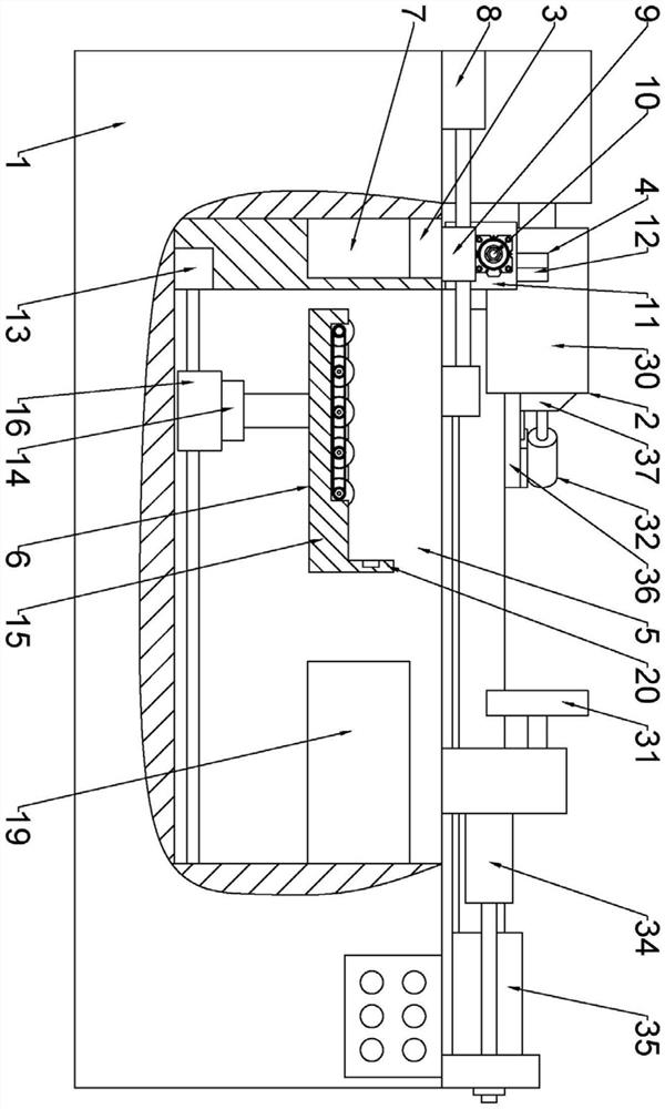
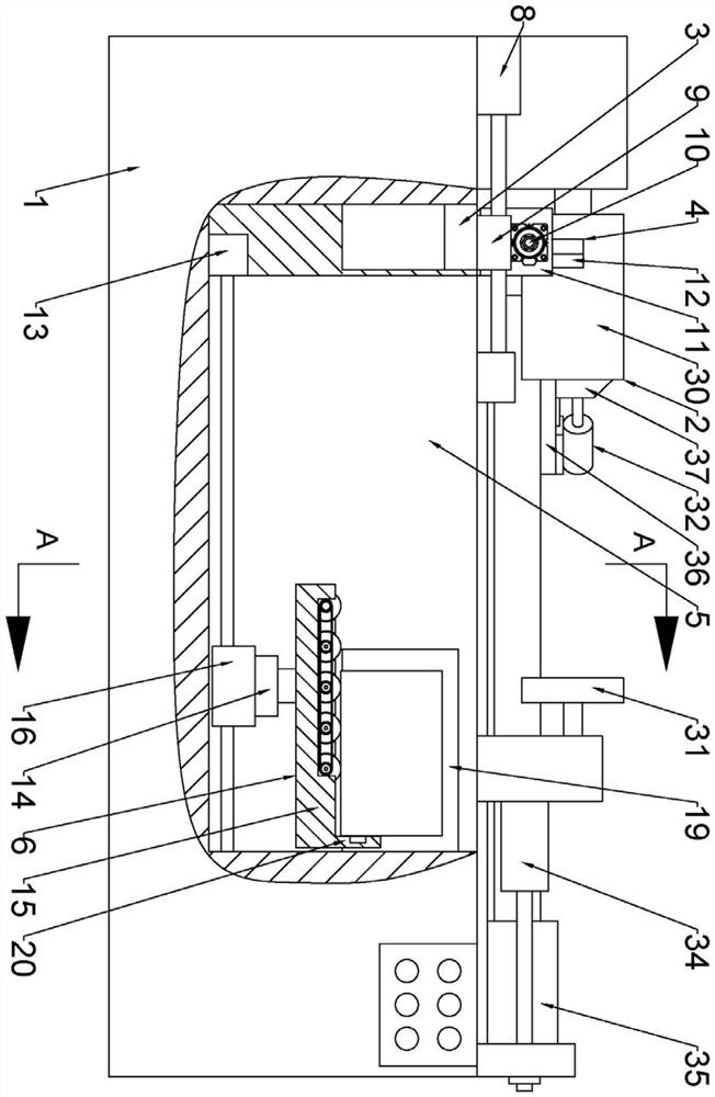
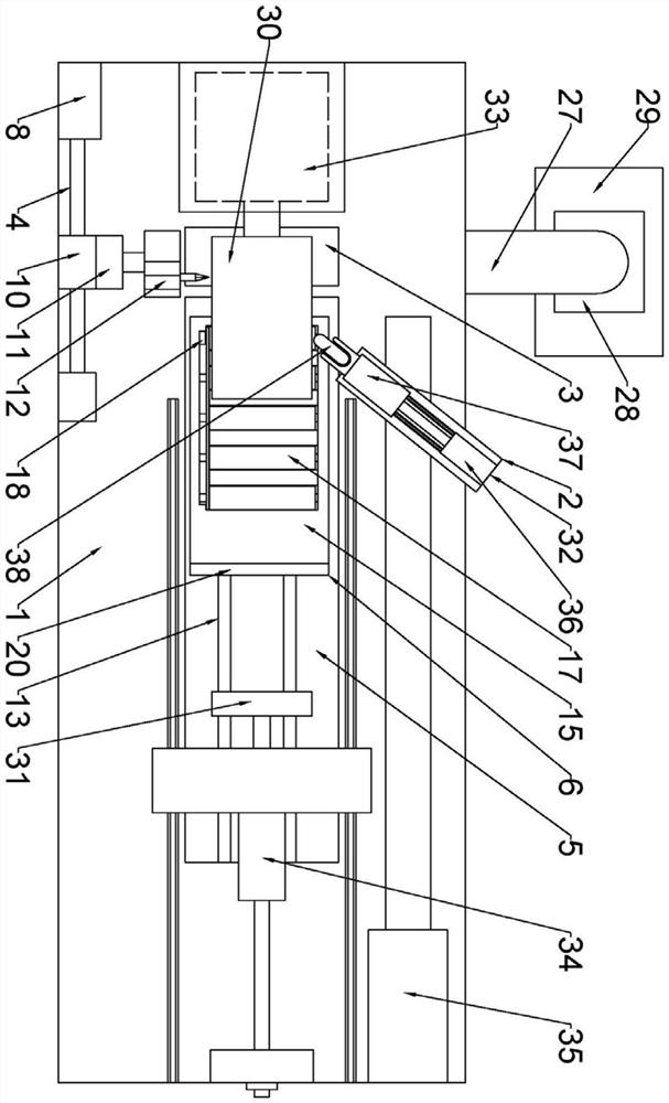
[0037] Such as figure 1 , figure 2 with image 3 In the described embodiment, a spinning equipment unloading mechanism, which includes a console 1, the console 1 is provided with a spinning assembly 2, a waste tank 3, a cutting assembly 4 and a discharge tank 5, spinning The assembly 2 is arranged overhead on the waste chute 3 and the discharge chute 5 respectively and is detachably connected with the operation table 1. The discharge chute 5 is located on one side of the waste chute 3. A discharge assembly 6 is arranged in the discharge chute 5, and the waste material The side wall of the groove 3 is provided with a waste discharge channel 7, the cutting assembly 4 includes a screw motor-8, the screw motor-8 is located on the other side of the waste tank 3 and is detachably connected with the console 1, the screw motor-8 The output end of t...


PUM


Abstract

The discharging mechanism of the spinning equipment comprises an operation table, a spinning assembly, a waste groove, a cutting assembly and a discharging groove are arranged on the operation table, the spinning assembly is arranged on the waste groove and the discharging groove in an overhead mode and detachably connected with the operation table, the discharging groove is located on one side of the waste groove, and the cutting assembly is detachably connected with the discharging groove. A discharging assembly is arranged in the discharging groove, a waste discharging channel is formed in the side wall of the waste groove, the cutting assembly comprises a first lead screw motor, the first lead screw motor is located on the other side of the waste groove and detachably connected with the operation table, and a sliding block is arranged at the output end of the first lead screw motor. The sliding block is in sliding connection with the operation table in the length direction of the operation table under driving of the first lead screw motor, a first rotating motor is detachably installed on the sliding block, a first air cylinder is connected to the output end of the first rotating motor, the output end of the first air cylinder faces the waste groove and is connected with a clamp, and a cutting tool corresponding to the spinning assembly is detachably installed on the clamp. The method has the beneficial effect that waste materials do not need to be manually treated.

Description

technical field [0001] The invention relates to the related technical field of spinning equipment, in particular to a spinning equipment unloading mechanism and a unloading method thereof. Background technique [0002] Spinning is to fix the flat or hollow blank on the mold of the spinning machine. While the blank is rotating with the main shaft of the bed, the blank is pressed with a spinning wheel or a driving rod to cause local plastic deformation. Spinning is a special forming method. The spinning method can complete the deep drawing, flanging, shrinking, bulging and curling of various shapes of rotating bodies. [0003] In the prior art, the spinning equipment mainly has the following problems: First, the finished products after spinning often need to be unloaded manually, which is time-consuming and labor-intensive; at the same time, because the surface of the finished products after spinning has a relatively high temperature, the operator It is often necessary to wa...

Claims


Application Information

Patent Timeline
Patent Type & Authority Applications(China)
IPC IPC(8): B21D45/06B21D22/14B21C51/00B21D43/20
CPCB21D45/06B21D22/14B21C51/00B21D43/20
Inventor 黄和钦潘文靖王景学谢凯翁君飞王小娟
Owner 宁波五谷金属制品有限公司
Why Eureka
Try Eureka