
Columnar plug-in screw turning machine

A screw machine and plug-in technology, applied in the field of plug-in processing equipment, can solve the problems of long time consumption, waste of manpower, low work efficiency, etc., achieve the effect of accurate hole position and improve work efficiency

Pending Publication Date: 2022-05-13
温州盛时利智能装备股份有限公司
View PDF0 Cites 0 Cited by
  • Summary
  • Abstract
  • Description
  • Claims
  • Application Information

AI Technical Summary

Problems solved by technology

[0002] The front and rear ends of the columnar insert are hollow, the front end needs to be screwed into the screw, and the rear end is provided with a pin that can be inserted into it. The screw hole in the front end of the columnar insert needs to be screwed into the screw manually, usually by manually screwing in the screw directly or by Manually load the material and adjust the direction of the columnar insert so that the screw hole of the columnar insert faces upwards, and then screw it through the screw-in device. If there are multiple screw holes on the columnar insert, it needs to be manually transferred to another one to be screwed in. Adjust the position and direction of the screw device before screwing in the screw, resulting in a waste of a lot of manpower, and it takes a long time to operate and the work efficiency is low. To screw in the screws, in order to solve this problem, a device is needed to screw in the screws and collect the plug-ins that have completed the process by automatically completing the conveying and loading of the mechanical equipment

Method used


Image

  • Columnar plug-in screw turning machine
  • Columnar plug-in screw turning machine
  • Columnar plug-in screw turning machine

Examples


Embodiment

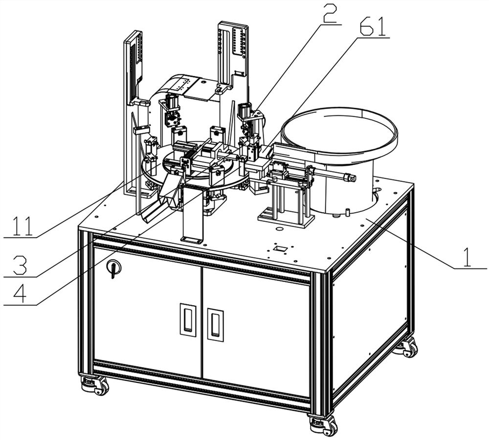
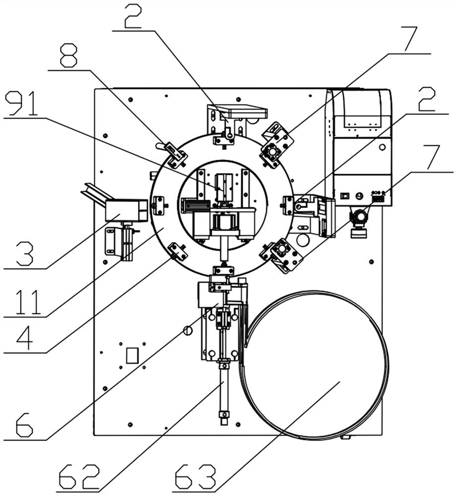
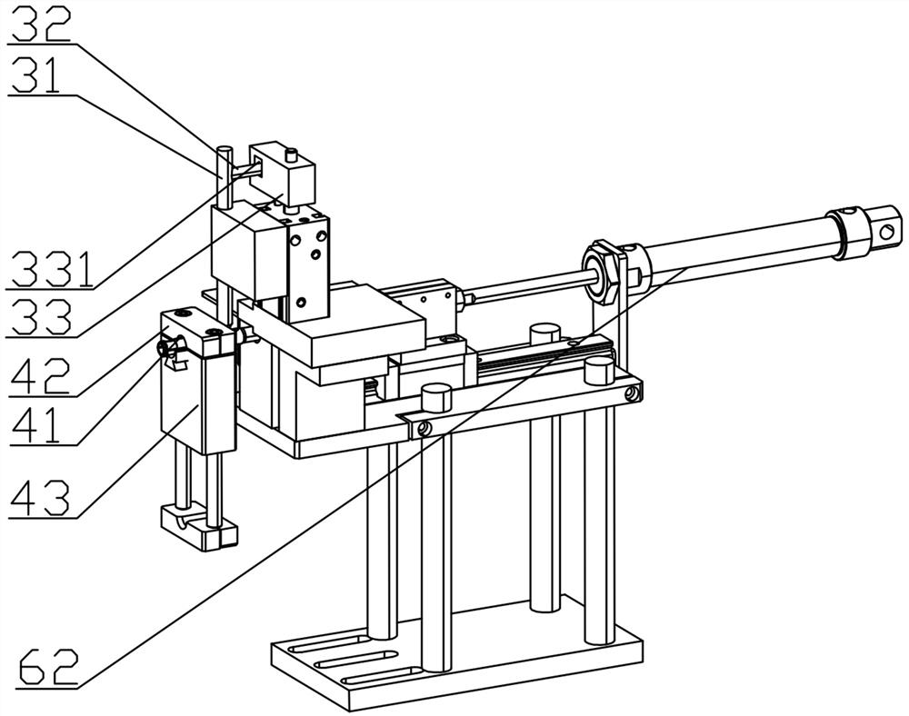
[0025] Screwdrivers with columnar inserts, such as Figure 1-4 As shown, it includes a frame 1, and the frame 1 is provided with a delivery platform 11, a screw device 2 and a plug-in adjustment device. The delivery platform 11 can be linear or turntable, such as figure 1 As shown, in this embodiment, taking the conveying platform 11 as a turntable as an example, the conveying platform 11 is an annular turntable, the screw-in device and the plug-in adjustment device are arranged on the outer peripheral side of the turntable, and the rotating power source 51 and the ejection cylinder 91 are arranged On the inner peripheral side of the turntable, the rotating power source 51 and the ejection cylinder 91 do not rotate together with the turntable, so that its working position is fixed, and the turntable only plays the movement of the plug-in fixing device transferred thereon. Screwing in the screw device 2 belongs to the equipment known to those skilled in the art, and its specifi...


PUM


Abstract

The invention relates to the field of plug-in machining equipment, and discloses a columnar plug-in screw turning machine which comprises a rack, a conveying platform, a screw turning device and a plug-in direction adjusting device are arranged on the rack, the plug-in direction adjusting device comprises a limiting mechanism, a plug-in fixing mechanism is arranged on the conveying platform, and a limiting hole allowing a plug-in to axially pass through is formed in the plug-in fixing mechanism. The inserting piece can rotate in the limiting hole in the circumferential direction, the inserting piece direction adjusting device is provided with a matching part in transmission connection with the rotating power source, and the matching part is connected with the inserting piece. The limiting mechanism comprises a coordination needle in transmission connection with the positioning power source, and when the matching part is connected with the inserting piece, the center axis of the coordination needle is located in the plane where the center axis of the bolt hole is located; the plug-in is conveyed through the conveying platform, the plug-in direction adjusting device and the limiting mechanism are respectively matched with the plug-in so as to adjust the direction of the plug-in to the correct direction of screwing a screw, and then the plug-in with the adjusted direction is automatically conveyed to the screw screwing device to be automatically screwed into the screw.

Description

technical field [0001] The invention relates to the field of plug-in processing equipment, in particular to a columnar plug-in screwing machine. Background technique [0002] The front and rear ends of the columnar insert are hollow, the front end needs to be screwed into the screw, and the rear end is provided with a pin that can be inserted into it. The screw hole in the front end of the columnar insert needs to be screwed into the screw manually, usually by manually screwing in the screw directly or by Manually load the material and adjust the direction of the columnar insert so that the screw hole of the columnar insert faces upwards, and then screw it through the screw-in device. If there are multiple screw holes on the columnar insert, it needs to be manually transferred to another one to be screwed in. Adjust the position and direction of the screw device before screwing in the screw, resulting in a waste of a lot of manpower, and it takes a long time to operate and t...

Claims


Application Information

Patent Timeline
IPC IPC(8): B23P19/00B23P19/06
CPCB23P19/001B23P19/006B23P19/06
Inventor 杨忠将吴立发
Owner 温州盛时利智能装备股份有限公司
Learn More