Hollow insulator and glass fiber tube depoling device

A technology of insulators and glass fiber tubes, applied in the field of insulator manufacturing, can solve the problems of high labor intensity and high labor costs, and achieve the effect of improving the overall strength, small volume and weight, and large operable space

Pending Publication Date: 2022-05-13
HENAN PINGGAO ELECTRIC
View PDF9 Cites 0 Cited by
  • Summary
  • Abstract
  • Description
  • Claims
  • Application Information

AI Technical Summary

Problems solved by technology

[0005] The purpose of the present invention is to provide a hollow insulator and glass fiber tube core removal device to solve the problem that two operators are required to operate the insulator demoulding tooling in the prior art, and manual force is required to fix the mandrel, resulting in relatively high labor intensity. Large technical issues with high labor costs

Method used


Image

  • Hollow insulator and glass fiber tube depoling device
  • Hollow insulator and glass fiber tube depoling device
  • Hollow insulator and glass fiber tube depoling device

Examples


Embodiment 1

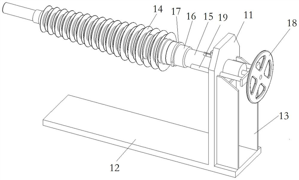
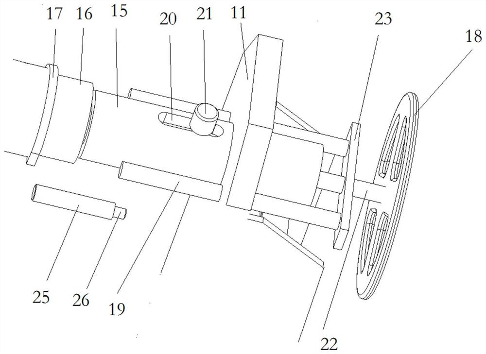
[0038] The hollow insulator and glass fiber tube core stripping device of the present invention is suitable for the demoulding of hollow insulators and glass fiber tubes. In this embodiment, the hollow insulator and the glass fiber tube core stripping device are used to demould the hollow insulator 14 . Such as figure 1 As shown, the hollow insulator and glass fiber tube core removing device includes a support frame and a pushing part for pushing the hollow insulator 14 . The support frame includes a vertical plate 11, and the pushing parts are movably assembled on the vertical plate 11 along the horizontal direction, and the vertical plate 11 is fixed on the bottom plate 12, and the bottom plate 12 is used to extend along the length direction of the hollow insulator 14 to increase the supporting area of ​​the support frame , improve the stability of the support frame. Moreover, two reinforcing plates 13 arranged in parallel and spaced apart are provided at the junction of t...

Embodiment 2

[0047] The difference between this embodiment and Embodiment 1 is that in Embodiment 1, the support frame includes a bottom plate 12 extending along the length direction of the hollow insulator or fiberglass tube, and a reinforcing plate 13 is arranged between the bottom plate 12 and the vertical plate 11 . In this embodiment, on the premise that the connection strength between the bottom plate 12 and the vertical plate 11 can meet the requirements of use, the reinforcing plate can be omitted. In other embodiments, the supporting frame includes a circular platform at the bottom and a vertical plate fixed on the circular platform.

Embodiment 3

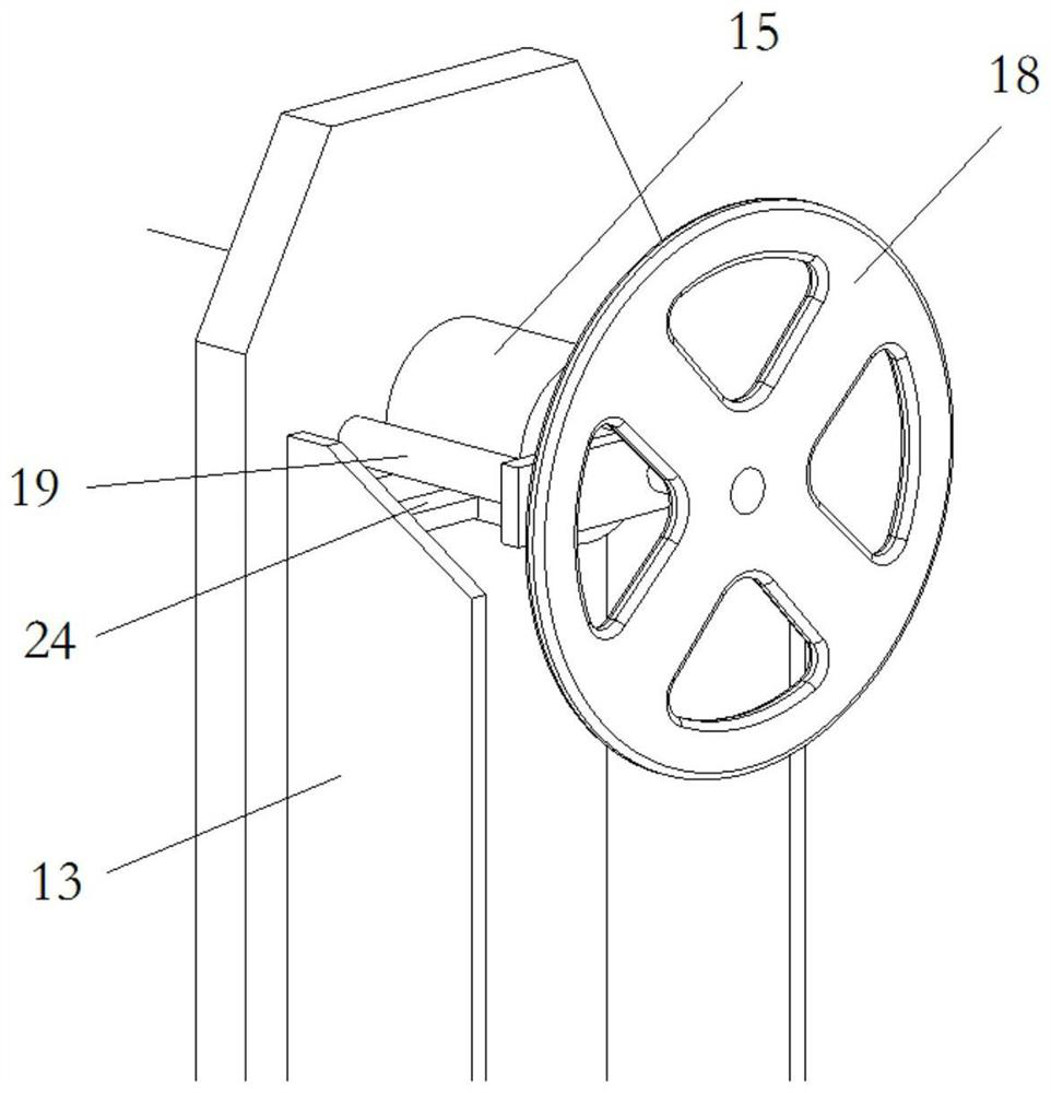
[0049] The difference between this embodiment and Embodiment 1 is that in Embodiment 1, the supporting blocks 24 are fixed on opposite sides of the two reinforcing plates 13 to support the end of the push rod away from the hollow insulator or the glass fiber tube. In this embodiment, the support block is fixed on the side of the vertical plate away from the hollow insulator or the glass fiber tube. In other embodiments, if the guide length between the ejector rod and the vertical plate is relatively large and the weight of the hand wheel is not enough to cause the ejector rod to deflect as a whole, the support block can also be eliminated.


PUM


Abstract

The invention relates to a hollow insulator and a glass fiber tube depoling device. The hollow insulator and glass fiber tube depoling device comprises a supporting frame and a pushing component used for pushing a hollow insulator or a glass fiber tube, the pushing component is movably assembled on the supporting frame in the horizontal direction, and the supporting frame comprises a mounting sleeve which is horizontally arranged in an overhanging mode. The mounting sleeve is provided with a positioning hole for a core body in a hollow insulator or a glass fiber tube to penetrate in in a matched manner so as to support the core body, a limiting hole is formed in the side wall of the mounting sleeve, and the limiting hole is used for being arranged corresponding to a through hole in the core body when the core body penetrates into the mounting sleeve; the depoling device further comprises a stop pin which is used for being inserted into the limiting hole and the penetrating hole at the same time so as to prevent the core body from being depoled from the mounting sleeve. The pushing component comprises at least two ejector rods located on the two sides of the limiting hole in the circumferential direction of the mounting sleeve, the ejector rods extend in the axial direction of the mounting sleeve, and the ejector rods are used for pushing the hollow insulator or the glass fiber tube. As the core body is fixed on the mounting sleeve, external force does not need to be applied to fix the core body.

Description

technical field [0001] The invention relates to the technical field of insulator manufacturing, in particular to a hollow insulator and a glass fiber tube core removing device. Background technique [0002] Composite insulators will generate a large injection pressure during the shed injection process. In order to protect the inner glass fiber tube from being broken under pressure, a support core is often added inside it. During the injection process, the injection pressure of the rubber material passes through the glass fiber tube. Applied on the surface of the core body, the glass fiber tube and the core body are in close contact. Under the high-pressure injection force of some tapered insulators, the tightness of the glass fiber tube and the core body is more prominent, which makes the glass fiber tube not well from the core. Remove from the body surface. Moreover, in the winding production of glass fiber tubes, the glass fibers impregnated with epoxy resin need to be wo...

Claims


Application Information

Patent Timeline
Patent Type & Authority Applications(China)
IPC IPC(8): B29C33/44H01B19/00B29L31/34
CPCB29C33/44H01B19/00B29L2031/3412
Inventor 刘洋张倩司文凯王保元胡泽涛李壮优陈巧玲杨青箐张振飞赵帅超席克会王瑞于环邓函李宁李彩娜段延伟
Owner HENAN PINGGAO ELECTRIC
Why Eureka
Try Eureka