Pull rod mechanism of injection seat of injection molding machine

A tie rod mechanism and injection seat technology, applied in the field of injection molding machine equipment, can solve the problems of poor guiding accuracy, high manufacturing cost, large guiding resistance, etc., and achieve the effects of compact mechanism design, reduced assembly cost, and fast response speed.

Pending Publication Date: 2022-05-13
广东昊天精密机械有限公司
View PDF0 Cites 1 Cited by
  • Summary
  • Abstract
  • Description
  • Claims
  • Application Information

AI Technical Summary

Problems solved by technology

This structure has the problems of poor guiding accuracy and large guiding resistance, which leads to uneven injection resistance of the injection platform, slow response speed and low transmission efficiency, thus affecting the quality of injection molding, and the pull rod mechanism of the injection platform of the electric injection molding machine with this structure The structure is complex, time-consuming and labor-intensive, the manufacturing cost is high, and it is not easy to produce and assemble

Method used


Image

  • Pull rod mechanism of injection seat of injection molding machine
  • Pull rod mechanism of injection seat of injection molding machine
  • Pull rod mechanism of injection seat of injection molding machine

Examples


Embodiment Construction

[0026] The following will clearly and completely describe the technical solutions in the embodiments of the present invention with reference to the accompanying drawings in the embodiments of the present invention. Obviously, the described embodiments are only some, not all, embodiments of the present invention. Based on the embodiments of the present invention, all other embodiments obtained by persons of ordinary skill in the art without creative efforts fall within the protection scope of the present invention.

[0027] The present invention will be further explained below in conjunction with the accompanying drawings and specific embodiments. It should be understood that the following specific embodiments are only used to illustrate the present invention and are not intended to limit the scope of the present invention. It should be noted that the words "front", "rear", "left", "right", "upper" and "lower" used in the following description refer to the directions in the draw...


PUM


Abstract

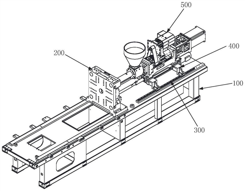
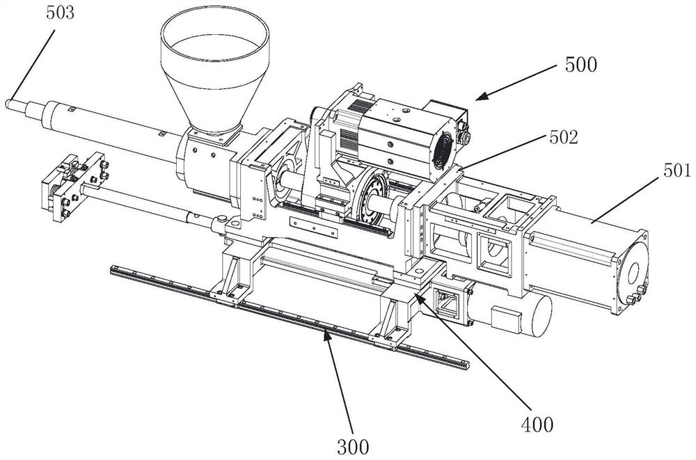
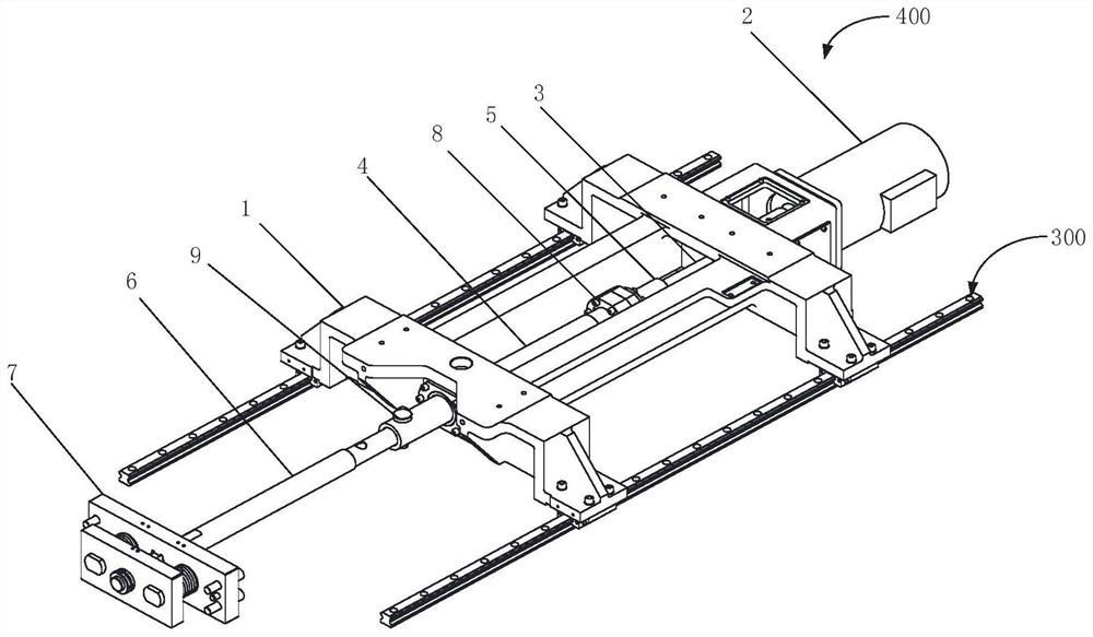
The invention provides a pull rod mechanism of an injection seat of an injection molding machine, and belongs to the technical field of injection molding machine equipment.The injection seat of the injection molding machine comprises a machine base, a head plate and a linear guide rail, the head plate and the linear guide rail are arranged on the machine base, a slidable pull rod mechanism is arranged on the linear guide rail and connected with the head plate, and an electric injection mechanism is arranged on the pull rod mechanism. The pull rod mechanism comprises an injection table support, a motor is fixedly arranged at one end of the injection table support, an output shaft of the motor is connected with one end of a lead screw, the lead screw is sleeved with a pull rod shaft sleeve, the pull rod shaft sleeve moves front and back in the length direction of the lead screw, and one end of the pull rod shaft sleeve is fixedly connected with a lead screw nut arranged on the lead screw. The other end of the pull rod shaft sleeve is connected with one end of the pull rod shaft, and is provided with a touch component for limiting the movement of the injection seat of the injection molding machine. The pull rod mechanism of the injection seat of the injection molding machine is compact in design, small in overall size, high in precision, high in response speed, high in transmission efficiency, suitable for various injection molding machine types, convenient to assemble and beneficial to reducing the assembly cost.

Description

technical field [0001] The invention relates to the technical field of injection molding machine equipment, in particular to a tie rod mechanism of an injection seat of an injection molding machine. Background technique [0002] The existing pull rod mechanism of the injection seat of the electric injection molding machine usually adopts the mechanism of biaxial guidance and double bearing. The mechanism of biaxial guidance and double bearing is: the push plate of the injection base is supported by two guide rods, and the screw rod applied with power pushes the push plate of the injection base. The push plate of the injection base pushes the two bearing shafts to realize the forward and backward of the injection base. This structure has the problems of poor guiding accuracy and large guiding resistance, which leads to uneven injection resistance of the injection platform, slow response speed and low transmission efficiency, thus affecting the quality of injection molding, an...

Claims


Application Information

Patent Timeline
Patent Type & Authority Applications(China)
IPC IPC(8): B29C45/17
CPCB29C45/1747B29C45/17
Inventor 杨芳华陈作驰
Owner 广东昊天精密机械有限公司
Why Eureka
Try Eureka