Front pillar mounting structure

A technology for mounting structures and front pillars, which is applied in the automotive field, can solve the problems of complex sheet metal lap joints of mounting structures, affecting the residual torque of mounting nuts, and pollution of mounting points, and achieve accuracy and cost targets, reliable performance, and pollution elimination. Effect

Pending Publication Date: 2022-05-13
CHONGQING CHANGAN AUTOMOBILE CO LTD
View PDF0 Cites 0 Cited by
  • Summary
  • Abstract
  • Description
  • Claims
  • Application Information

AI Technical Summary

Problems solved by technology

In addition, the front pillar assembly installation structure sheet metal overlap is complicated. In order to avoid corrosion, the joints between the upper part of the front wheel bulge and each lap edge need to be scraped to form a sealant line 112. Due to limited space, each lap The distance between the edge joint and the mounting point of the front strut assembly is relatively close, and the scraping treatment is likely to pollute the mounting point of the front strut assembly and affect the residual torque of the mounting nut of the front strut assembly

Method used


Image

  • Front pillar mounting structure
  • Front pillar mounting structure
  • Front pillar mounting structure

Examples


Embodiment Construction

[0029] The invention will be further described below in combination with the accompanying drawings.

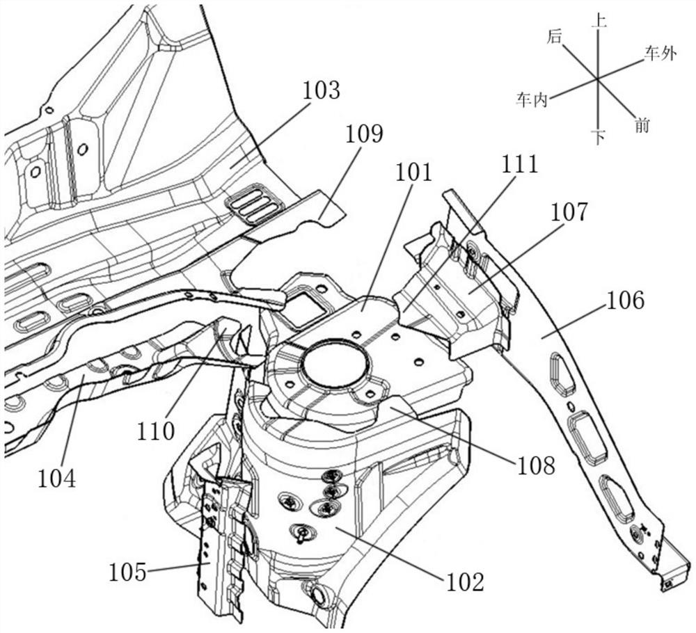
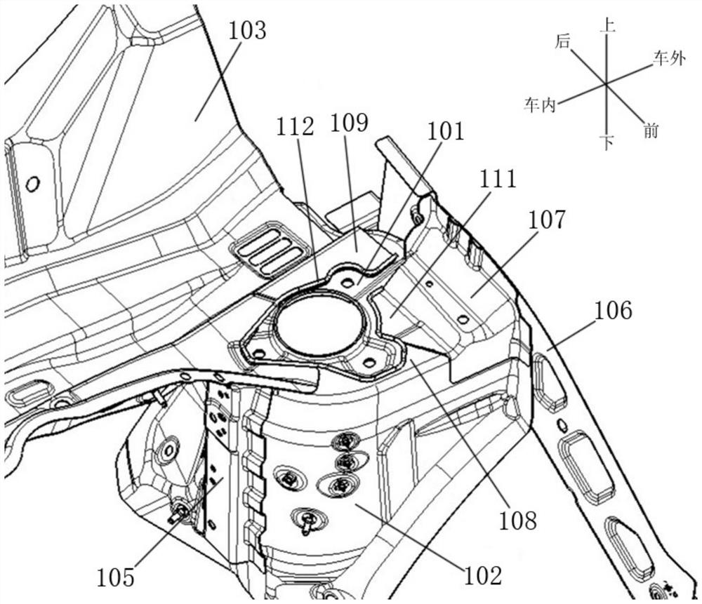
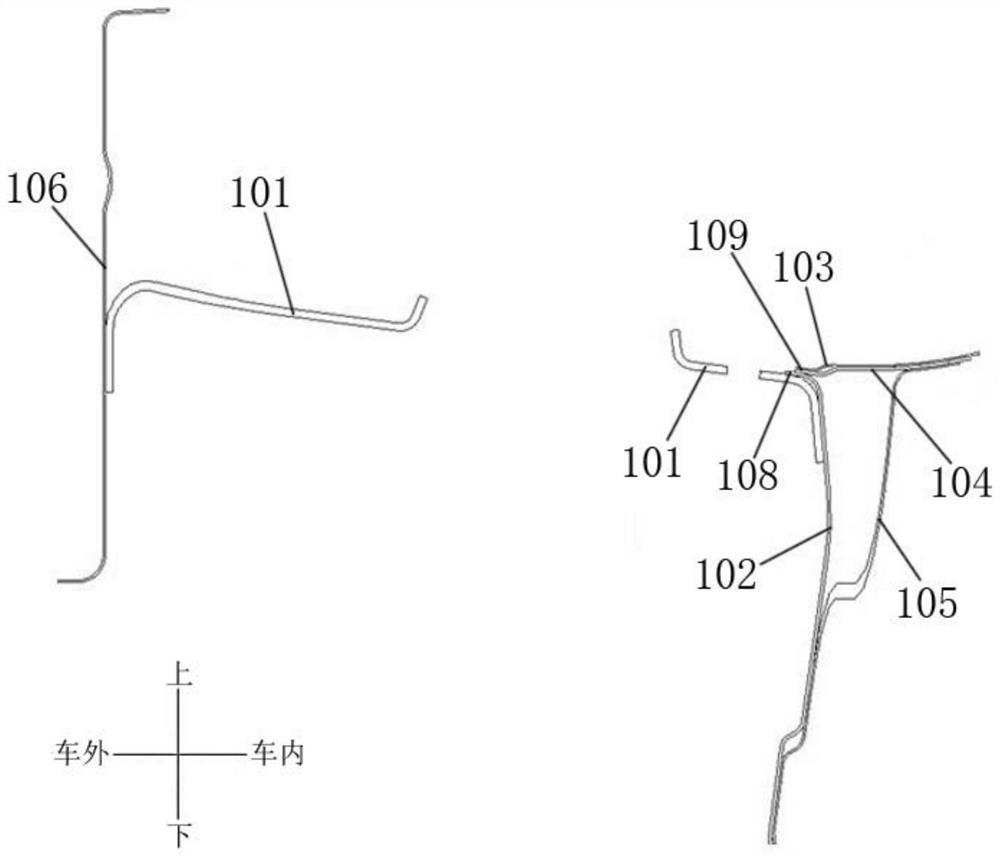
[0030] as Figures 5 to 8 A front pillar mounting structure shown in the figure includes a front wheel bulge upper section 1, a front wheel bulge middle section 2, a heater pressure chamber plate 3, a heater pressure chamber plate reinforcement 4 and a fender mounting plate 6; The front wheel bulge upper section 1 includes a top wall 11, a first side wall 12, a second side wall 13 and a third side wall 14. The first side wall 12 extends downward from the inner and front edges of the top wall 11, the second side wall 13 extends backward and downward from the rear edge of the top wall 11, the second side wall 13 tilts backward from top to bottom, and the second side wall 13 extends downward from the outer edge of the top wall 11; The upper end of the front wheel bulging middle section 2 is provided with a first overlapping edge 21, which is overlapped on the first side wall 12; The p...


PUM


Abstract

The invention relates to a front pillar mounting structure which comprises a front wheel bulge upper section, a front wheel bulge middle section, a warm air blower pressure chamber plate, a warm air blower pressure chamber plate reinforcer and a fender mounting plate. The front wheel bulge upper section comprises a top wall, a first side wall, a second side wall and a third side wall; a first overlapping edge overlapped on the first side wall is arranged on the front wheel bulge middle section; a second overlapping edge overlapped on the second side wall is arranged on the fan heater pressure chamber plate; a third overlapping edge overlapped on the second side wall is arranged on the warm air blower pressure chamber plate reinforcer; the warm air blower pressure chamber plate reinforcing piece is in lap joint with the third side wall. The device has the advantages of being simple in structure, reliable in performance, easy in precision control, low in cost and high in practicability, and the problem that installation points of the front supporting column assembly are polluted due to glue scraping is relieved or even eliminated.

Description

technical field [0001] The invention relates to an automobile, in particular to a front pillar mounting structure. Background technology [0002] as Figures 1 to 4 As shown, the front strut mounting structure in the prior art includes a front wheel drum upper section 101, a front wheel drum middle section 102 and a fender mounting plate 106 welded together. A plurality of mounting holes are arranged on the wheel drum upper section 101, the lower end of the front strut assembly is fixedly connected to the front wheel drum upper section 101 through bolts matched with the mounting holes, and the front wheel drum middle section 102 is provided with a first overlapping edge 108 overlapped downward on the upper surface of the front wheel drum upper section 101, In order to ensure the rigidity of the front strut mounting point and the torsional mode of the engine compartment, the front wheel drum middle section 102 is overlapped with the front wheel drum middle section reinforcement 105...

Claims


Application Information

Patent Timeline
Patent Type & Authority Applications(China)
IPC IPC(8): B62D25/04B62D27/06
CPCB62D25/04B62D27/06
Inventor 胡斌张兴华赵明张海清姚善明
Owner CHONGQING CHANGAN AUTOMOBILE CO LTD
Why Eureka
Try Eureka